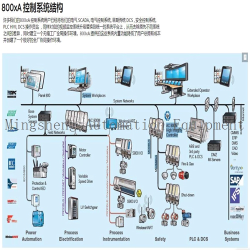
Home > Product > Gas turbine system > IS200DTAOH1ABA IS210DTAOH1AA Gas turbine module


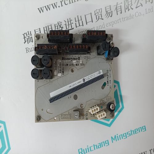
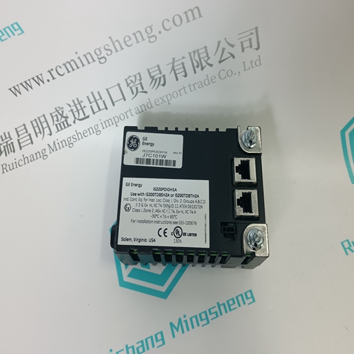
IS200DTAOH1ABA IS210DTAOH1AA Gas turbine module
- Product ID: IS200DTAOH1ABA IS210DTAOH1AA
- Brand: GE
- Place of origin: the United States
- Goods status: new/used
- Delivery date: stock
- The quality assurance period: 365 days
- Phone/WhatsApp/WeChat:+86 15270269218
- Email:stodcdcs@gmail.com
- Tags:IS200DTAOH1ABAIS210DTAOH1AAGas turbine module
- Get the latest price:Click to consult
IS200DTAOH1ABA IS210DTAOH1AA Gas turbine module
The CIS can have one of 64 addresses (address 0 to 63) on the slave expander bus. This address uniquely identifies the slave to the Multi-Function Processor (MFP) and must be the same as the address set in the MFP configuration (Function Code 79 specification 1). The address is set by the eight position address dipswitch (S1) shown in Figure 3-1. The six right switch positions (3 through 8) of S1 set the six bit CIS address. Positions 1 and 2 are not used and must remain in the closed position (see Figure 3-2). Table 3-1 is a binary address conversion table for setting S1.Prior to installation, you must set the module dipswitches and install jumpers to configure the I/O. You must configure the Termination Unit (TU) or Termination Module (TM) to accept the field device signals and output the CIS signals to the process.
Analog Output Default Switch (S2)
The analog output default switch (S2), shown in Figure 3-1, determines the CIS analog output default values. These are the values or levels for the analog outputs during system start-up (power up) or bus fault error (time-out). You can select either a 0 percent or 100 percent power up output. Selecting 0 percent will output 4 mA or 1 VDC; selecting 100 percent will output 20 mA or 5 VDC. Switch position 3 selects the value for Analog Output 1 (AO1) and position 6 selects the value for Analog Output 2 (AO2). S3 determines the mode of the output (current or voltage).
If the bus fault timer expires (times out)
the digital outputs de-energize and the analog outputs change to the default value selected. A time-out occurs when the slave does not receive a clock signal from the MFP. The time-out options are to hold or go to power up state. The outputs will stay at their current values during a time-out if the hold option is selected; they will change to the power up values (0 or 100 percent) if the go to power up state is selected. Position 2 selects the time-out option for AO1. Position 5 selects the time-out option for AO2. Section 2 explains the bus fault timer in more detail. Switch positions 1 and 4 are not used and should be in the closed position. Figure 3-3 shows the analog output default switch (S2); refer to Table 3-2 for the switch settings. Determine the requirements for your process and set the dipswitches to the positions shown in the table.
The main products
Spare parts spare parts, the DCS control system of PLC system and the robot system spare parts,
Brand advantage: Allen Bradley, BentlyNevada, ABB, Emerson Ovation, Honeywell DCS, Rockwell ICS Triplex, FOXBORO, Schneider PLC, GE Fanuc, Motorola, HIMA, TRICONEX, Prosoft etc. Various kinds of imported industrial parts
Products are widely used in metallurgy, petroleum, glass, aluminum manufacturing, petrochemical industry, coal mine, papermaking, printing, textile printing and dyeing, machinery, electronics, automobile manufacturing, tobacco, plastics machinery, electric power, water conservancy, water treatment/environmental protection, municipal engineering, boiler heating, energy, power transmission and distribution and so on.