Home > Product > DCS control system > 3BSC980006R358 Analog input module
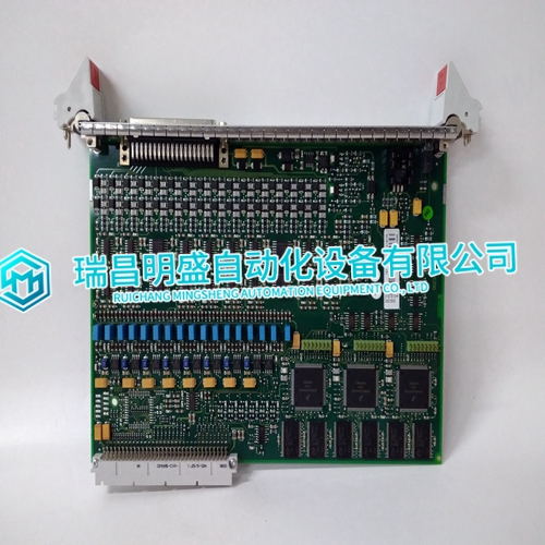
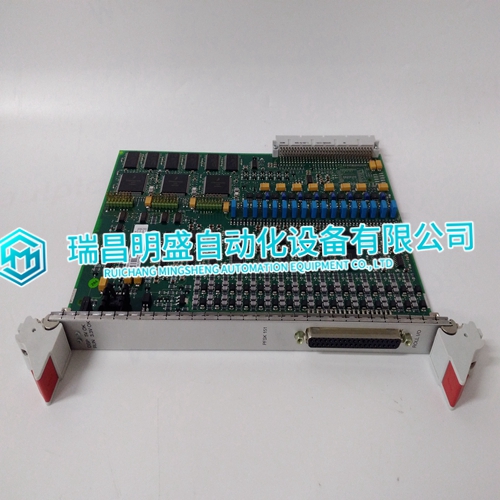
3BSC980006R358 Analog input module
- Product ID: 3BSC980006R358
- Brand: ABB
- Place of origin: The Swiss
- Goods status: new/used
- Delivery date: stock
- The quality assurance period: 365 days
- Phone/WhatsApp/WeChat:+86 15270269218
- Email:stodcdcs@gmail.com
- Tags:3BSC980006R358Analog input module
- Get the latest price:Click to consult
3BSC980006R358 Analog input module
Connect the hooded end of the termination cable from the TU/TM to the MMU backplane. To do this, insert the connector into the backplane slot in the same slot as the one assigned to the slave module. The latches should snap securely into place. 4. Align the module with the plastic guide rails in the MMU; gently slide the module in until the front panel is flush with the top and bottom of the MMU frame. 5. Push and turn the two captive retaining screws on the module faceplate one half turn to the latched position. It is latched when the slots on the screws are vertical and the open ends face the center of the module. (To remove the module, turn the module retaining screws to the unlatched position and gently slide it out).The CIS has three card edge connectors to supply logic power, establish slave expander bus communication and provide I/O (P1, P2, P3 respectively).
Installing the module in the MMU connects
the slave module to the logic power, necessary to drive the circuitry, at P1. It also connects P2 to the slave expander bus for communication with the MFP. P1 and P2 connection require no additional wiring or cabling. NOTE: You must install a dipshunt on the backplane of the MMU to connect the slave expander bus between the slave module and master module. Locate the modules so the bus can connect the modules or they will not communicate. Cable Connections The IMCIS02 uses either a NTCS02 or NICS01 for termination. See Figure 3-5 to determine the cables to use with the termination unit or module you are using. FUSING Fuse resistors for the analog outputs are soldered on the CIS module board. They are not intended for customer replacement. PRE-OPERATING ADJUSTMENTS You do not have to make any adjustments to the CIS prior to operating
START-UP PROCEDURES
The Multi-Function Processor (MFP) controls the start-up of the CIS module; it is fully automatic. Function Code (FC) 79 in the MFP configuration enables the CIS. Specification 1 (FC 79) is the slave module address. It must be the same as the address set on the address dipswitch (S1). The front panel LED (solid green) verifies that the module is enabled and communicating. This section explains the front panel indicator and start-up procedures for the Control I/O Slave module (IMCIS02). MODULE STATUS INDICATOR The Control I/O Slave (CIS) module has a front panel module status LED indicator to aid in system test and diagnosis. The location of the indicator is shown in Figure 4-1. Table 4-1 explains the three states of the status LED indicator (refer to Section 5 to determine corrective actions).
The main products
Spare parts spare parts, the DCS control system of PLC system and the robot system spare parts,
Brand advantage: Allen Bradley, BentlyNevada, ABB, Emerson Ovation, Honeywell DCS, Rockwell ICS Triplex, FOXBORO, Schneider PLC, GE Fanuc, Motorola, HIMA, TRICONEX, Prosoft etc. Various kinds of imported industrial parts
Products are widely used in metallurgy, petroleum, glass, aluminum manufacturing, petrochemical industry, coal mine, papermaking, printing, textile printing and dyeing, machinery, electronics, automobile manufacturing, tobacco, plastics machinery, electric power, water conservancy, water treatment/environmental protection, municipal engineering, boiler heating, energy, power transmission and distribution and so on.