Home > Product > DCS control system > ECPSR086370-001 controller card
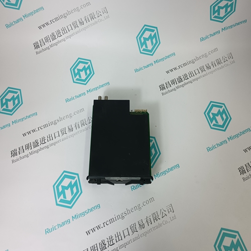
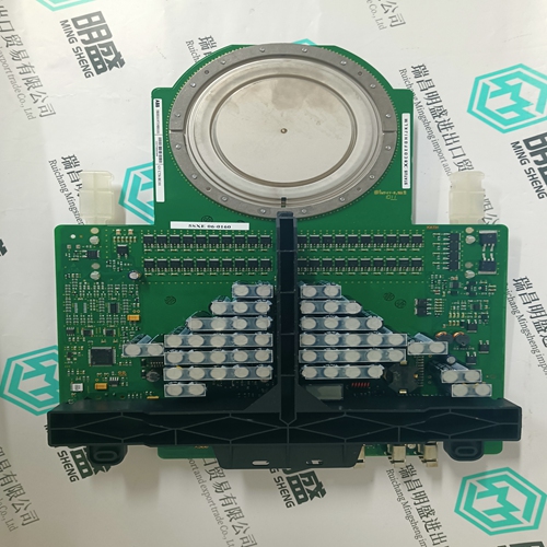
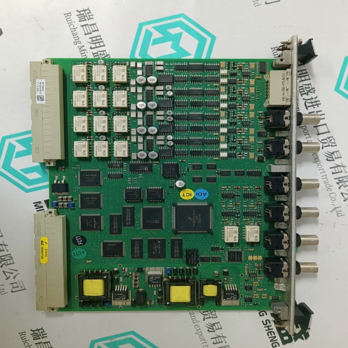
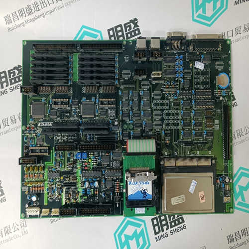
ECPSR086370-001 controller card
- Product ID: ECPSR086370-001
- Brand: ABB
- Place of origin: The Swiss
- Goods status: new/used
- Delivery date: stock
- The quality assurance period: 365 days
- Phone/WhatsApp/WeChat:+86 15270269218
- Email:stodcdcs@gmail.com
- Tags:ECPSR086370-001controller card
- Get the latest price:Click to consult
ECPSR086370-001 controller card
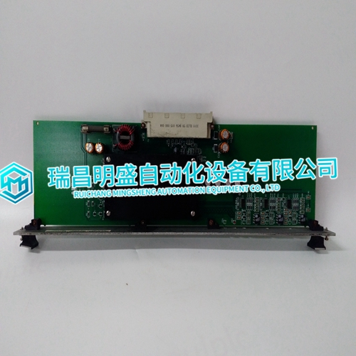
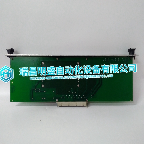
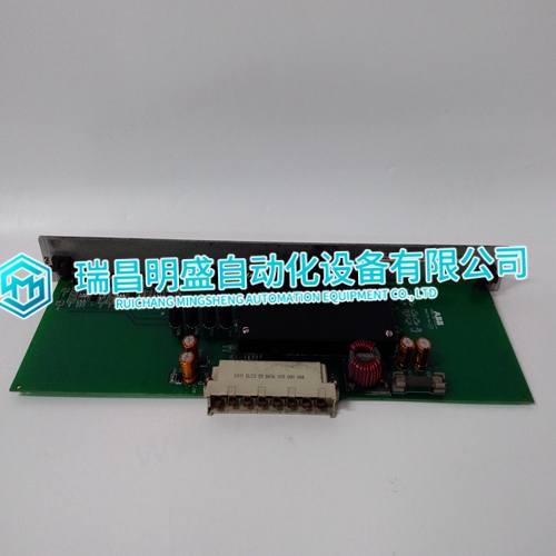
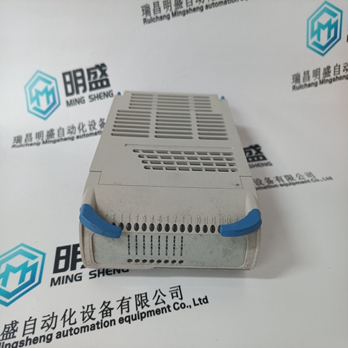
The DSO module consists of a single printed circuit board that occupies one slot in a module mounting unit (MMU). It outputs 16 separate digital signals through solid state circuits on the printed circuit board. Twelve outputs are isolated from each other; the remaining two pairs share common positive output lines. Two captive screws on the faceplate secure the module to the MMU. The upper two front panel red and greed LEDs indicate the module operating status. The 16 lower front panel red LEDs (group A and group B) display the module output states (ON or OFF). The DSO module has three card edge connectors for external signals and power (P1, P2 and P3). P1 connects to logic power (+5 VDC) that drives the module circuits. P2 connects the module to the I/O expander bus to communicate with a control module. P3 outputs the digital signals using a cable connected to a termination unit (TU) or a termination module (TM). The terminal blocks (physical connection points) for field wiring are on the TU or TM.
INSTRUCTION CONTENT
This instruction is divided into eight sections and four appendices. Read this instruction before installing or operating the IMDSO14 digital output module. A summary of section content follows: Introduction Contains a brief description, general usage information and technical specifications. Description and Operation Uses block diagrams and schematics to explain module operation and input circuitry. Installation Covers the preliminary steps to install the module and prepare for operation. It covers address switch settings, mounting, wiring connections, cabling and preoperational checks. used by those planning to purchase, install, operate, troubleshoot, maintain or replace these modules. Those working with the digital output module should have experience working with and know the precautions to take around AC/DC power. A knowledge of the INFI 90 OPEN system and electronic principles is also required.
Provides information on front panel indicators
and start-up procedures. Troubleshooting Explains the meaning of error indications and contains troubleshooting procedures.Contains scheduled maintenance tasks and procedures. Repair and Replacement Procedures Contains procedures that explain how to replace the module. Support Services Explains the services and training that Elsag Bailey makes available toul, their customers. Appendices Appendix A provides configuration information for the NTDI01 termination unit. Appendix B provides configuration information for the NIDI01 termination module. Appendix C provides configuration information for the NTDO02 termination unit. Appendix D provides a quick reference for module switch location and settings.
The main products
Spare parts spare parts, the DCS control system of PLC system and the robot system spare parts,
Brand advantage: Allen Bradley, BentlyNevada, ABB, Emerson Ovation, Honeywell DCS, Rockwell ICS Triplex, FOXBORO, Schneider PLC, GE Fanuc, Motorola, HIMA, TRICONEX, Prosoft etc. Various kinds of imported industrial parts
Products are widely used in metallurgy, petroleum, glass, aluminum manufacturing, petrochemical industry, coal mine, papermaking, printing, textile printing and dyeing, machinery, electronics, automobile manufacturing, tobacco, plastics machinery, electric power, water conservancy, water treatment/environmental protection, municipal engineering, boiler heating, energy, power transmission and distribution and so on.
