Home > Product > Gas turbine system > IS230SRTDH2A Gas turbine electric
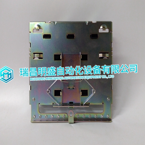
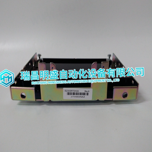
IS230SRTDH2A Gas turbine electric
- Product ID: IS230SRTDH2A
- Brand: GE
- Place of origin: the United States
- Goods status: new/used
- Delivery date: stock
- The quality assurance period: 365 days
- Phone/WhatsApp/WeChat:+86 15270269218
- Email:xiamen2018@foxmail.com
- Tags:IS230SRTDH2AGas turbine electric
- Get the latest price:Click to consult
IS230SRTDH2A Gas turbine electric
The data selector block drives the output circuits and lights the front panel output status LEDs. It uses data from the output register or default register to do this. During normal operation, it selects the output register data.
The default control logic block is a one bit latch register. It sends a signal to the data selector block to select either the default register data or the output register data during a time-out (indicating a control module error). This signal is dependent on the control module configuration (FC 83 specification S2). The bus fault detector in the I/O expander bus interface checks for a time-out condition. During a time-out, the data selector block normally selects the default register data. If a hold option is selected in FC 83, the default control logic circuits send a logic 1 to override the data selector. It causes the data selector to drive the outputs with the output register data instead of default data to maintain the outputs at their current values (hold).
Digital Output Circuits
Sixteen open collector transistors in the digital output block function as digital switches. Optocouplers for each output provide isolation between the module circuits and the process field device. All outputs are normally de-energized (OFF) until a signal from the data selector block causes them to energize (ON). The output circuits provide 1.5 kV isolation between output and logic circuits, and other output channels. NOTE: Due to the number of pins on the P3 connector, 12 outputs are separate while the remaining two pairs share output terminals. The positive (+) sides of outputs 7 and 8 are tied together for each group (refer to Table 5-4). They are not isolated from each other, but are isolated from the module circuitry.
Output Control Logic
An output register holds the data that controls the outputs. The I/O expander bus interface writes control module data to this register. This data, sent to the data selector, determines the output states (ON or OFF). Default data from the control module is sent to the default register. The control module configuration sets the default values (Function Code 128). The default register is reset to logic zeros during power up to drive the outputs to a de-energized state. FC 128 in the control module configuration selects the output values used to drive the output circuits in the event of a control module failure (time-out). If FC 128 is not defined, the outputs will go to a de-energized state during a time-out. Refer to BUS FAULT TIMER in this section for further explanation of time-out.
The main products
Spare parts spare parts, the DCS control system of PLC system and the robot system spare parts,
Brand advantage: Allen Bradley, BentlyNevada, ABB, Emerson Ovation, Honeywell DCS, Rockwell ICS Triplex, FOXBORO, Schneider PLC, GE Fanuc, Motorola, HIMA, TRICONEX, Prosoft etc. Various kinds of imported industrial parts
Products are widely used in metallurgy, petroleum, glass, aluminum manufacturing, petrochemical industry, coal mine, papermaking, printing, textile printing and dyeing, machinery, electronics, automobile manufacturing, tobacco, plastics machinery, electric power, water conservancy, water treatment/environmental protection, municipal engineering, boiler heating, energy, power transmission and distribution and so on.