Home > Product > DCS control system > P0926KP cable
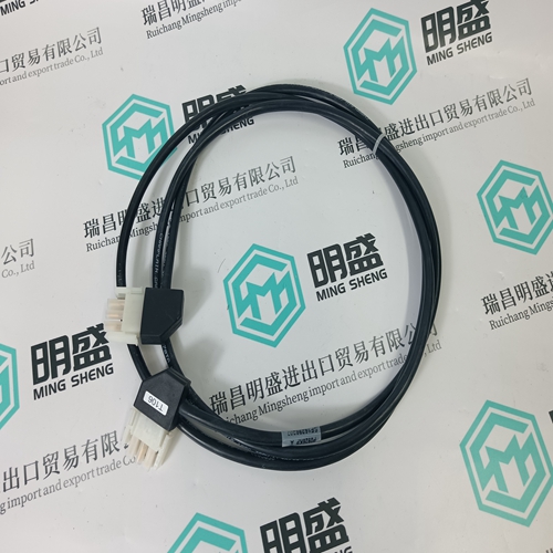
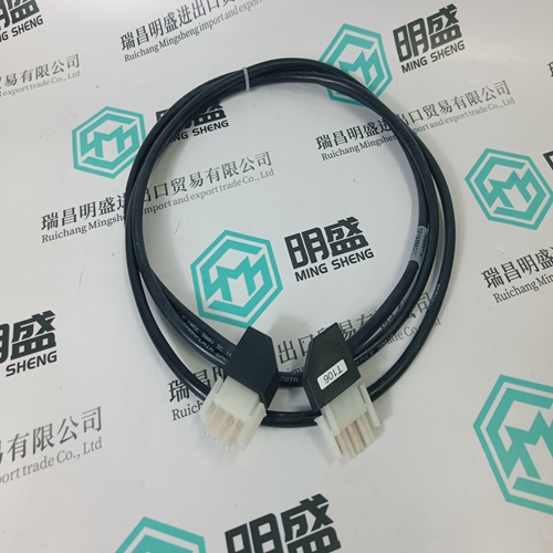
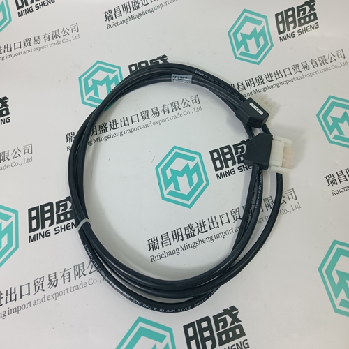
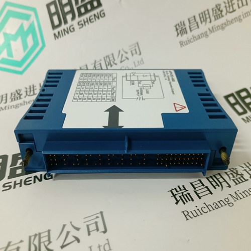
P0926KP cable
- Product ID: P0926KP
- Brand: FOXBORO
- Place of origin: The United States
- Goods status: new/used
- Delivery date: stock
- The quality assurance period: 365 days
- Phone/WhatsApp/WeChat:+86 15270269218
- Email:stodcdcs@gmail.com
- Tags:P0926KPcable
- Get the latest price:Click to consult
The main products
Spare parts spare parts, the DCS control system of PLC system and the robot system spare parts,
Brand advantage: Allen Bradley, BentlyNevada, ABB, Emerson Ovation, Honeywell DCS, Rockwell ICS Triplex, FOXBORO, Schneider PLC, GE Fanuc, Motorola, HIMA, TRICONEX, Prosoft etc. Various kinds of imported industrial parts
P0926KP cable
No other codes will normally be generated, but if they are, they are a diagnostic aid for the specialist. MTR": The value measured for MTR is displayed when the input 'AdjMTRInp' is enabled. During normal operation, the value entered for MTR on the HMI is displayed.REs": When the input 'AdjREsInp' is enabled, 123.0 is displayed initially until the resistance has been computed. This can take a maximum of 10 s after which the value measured for REs is displayed. During normal operation, the value entered for REs on the HMI is displayed. Normal operation: Neither of the two I/P's 'AdjMTRInp' and 'AdjREsInp' are disabled and injection is taking place. Note: Only one of the binary I/P's may be enabled at any one time, otherwise an error code is generated for the measurements Rfs, MTR and REs (see table below). Explanation of parameters: RunOnCPU defines the processing unit which runs the function. ParSet 4..1 Parameter for determining in which set of parameters a particular function is active (see Section 5.11.). Trip 01-08 defines the tripping channel activated by the tripping O/P of the function (matrix tripping logic). Trip 09-16 corresponds to Trip 01-08 (providing tripping unit fitted). Trip 17-24 corresponds to Trip 01-08 (providing tripping unit fitted). Trip 25-32 corresponds to Trip 01-08 (providing tripping unit fitted). Alarm-Delay Time between pick-up of the alarm stage and an alarm. Trip-Delay Time between pick-up of the tripping stage and a trip. RFs-AlarmVal Ground fault resistance setting for alarm. RFs for alarm must be greater than RFs for tripping. RFs-TripVal Ground fault resistance setting for tripping. REs Grounding resistor REs for primary system grounding. Where the grounding resistor is connected to the secondary of a v.t., its value related to the primary system R'Es must be entered. REs-2.Starpt The total grounding resistance of a 2nd. star-point in the zone of protection.
Setting procedure
How accurately Rfs is measured depends on the values entered for REs and MTR. Therefore check the settings and correct them if necessary by connecting resistors between 100 and 10 k between the star-point and ground with the generator at a standstill. The protection function provides a convenient way of setting these two parameters in the software by switching its mode using the input 'AdjMTRInp' or 'AdjREsInp'. This is the recommended procedure. In this mode, the settings of the parameters 'MTR' and 'REs' are calculated with the aid of simulated ground fault resistances. The two parameters are displayed continuously in the window for measured values. Should the values of REs and MTR determined by the adjustment mode differ from their nominal values, the calculated values are the preferred values.Setting instructions The value of 'RFs-Setting' for alarm must always be greater than that of 'RFs-Setting' for tripping. Both alarm and tripping stages have their own timers. Typical delays used for the 100 % ground fault protection are in the range of seconds. Settings: 'RFs-Setting' for tripping 'RFs-Setting' for alarm Delay for tripping Delay for alarm Grounding resistor REs Measuring transformer ratio (MTR).
