Home > Product > DCS control system > LSP086388-001 Serial links module
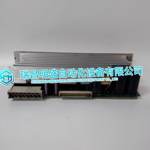
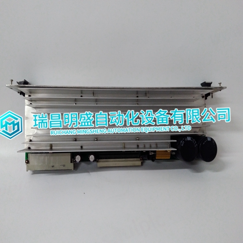
LSP086388-001 Serial links module
- Product ID: LSP086388-001
- Brand: ABB
- Place of origin: The Swiss
- Goods status: new/used
- Delivery date: stock
- The quality assurance period: 365 days
- Phone/WhatsApp/WeChat:+86 15270269218
- Email:xiamen2018@foxmail.com
- Tags:LSP086388-001Serial links module
- Get the latest price:Click to consult
LSP086388-001 Serial links module
Use the static grounding wrist strap when installing and removing modules. Static discharge may damage static sensitive devices on modules in a cabinet. Use grounded equipment and static safe practices when working with static sensitive devices. 1. Use Static Shielding Bag. Keep the module in its static shielding bag until you are ready to install it in the system. Save the bag for future use. 2. Ground Bags before Opening. Before opening a bag containing an assembly with static sensitive devices, touch it to the equipment housing or ground to equalize charges. 3. Avoid Touching Circuitry. Handle assemblies by the edges; avoid touching the circuitry. 4. Avoid Partial Connection of Static Sensitive Devices. Verify that all devices connected to the modules are properly grounded before using them. 5. Ground Test Equipment. 6. Use an Antistatic Field Service Vacuum. Remove dust from the cards if necessary. 7. Use a Grounded Wrist Strap. Connect the wrist strap to the appropriate grounding plug Do Not Use Lead Pencils to Set Dipswitches. To avoid contamination of switch contacts that can result in unnecessary circuit board malfunction, do not use a lead pencil to set a dipswitch.
UNPACKING AND INSPECTION
Examine the hardware immediately to verify it has not been damaged in transit. 2. Notify the nearest Elsag Bailey Sales Office of any such damage. 3. File a claim for any damage with the transportation company that handled the shipment. 4. Use the original packing material and container to store the hardware. 5. Store the hardware in an environment of good air quality, free from temperature and moisture extremes.Prior to installation, set the module S1 address switch. Configure the termination unit (TU) or termination module (TM) to output the digital signals from the DSO to the field devices. Refer to the appendices at the back of this instruction for configuration information. NOTE: Due to the number of pins on the P3 connector, 12 outputs are separate while the remaining two pairs share output terminals. The positive (+) side of point 7 and 8 are tied together for each group
Address Selection Switch (S1)
The DSO can have one of 64 addresses (address 0 to 63) on the I/O expander bus. This address uniquely identifies the I/O module to the control module and must be the same as the address set in the control module configuration (Function Code (FC) 83 specification S1). The address is set by the eight position address dipswitch (S1) shown in Figure 3-1. The six right switch positions (3 through 8) of S1 set the six bit DSO address. Positions 1 and 2 are not used and must remain in the closed position (Fig. 3-2). Table 3-1 is a binary address conversion table for setting S1.
The main products
Spare parts spare parts, the DCS control system of PLC system and the robot system spare parts,
Brand advantage: Allen Bradley, BentlyNevada, ABB, Emerson Ovation, Honeywell DCS, Rockwell ICS Triplex, FOXBORO, Schneider PLC, GE Fanuc, Motorola, HIMA, TRICONEX, Prosoft etc. Various kinds of imported industrial parts
Products are widely used in metallurgy, petroleum, glass, aluminum manufacturing, petrochemical industry, coal mine, papermaking, printing, textile printing and dyeing, machinery, electronics, automobile manufacturing, tobacco, plastics machinery, electric power, water conservancy, water treatment/environmental protection, municipal engineering, boiler heating, energy, power transmission and distribution and so on.