Home > Product > PLC programmable module > NI SCXI-1325 Voltage dc module
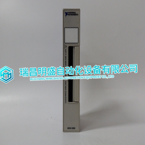
NI SCXI-1325 Voltage dc module
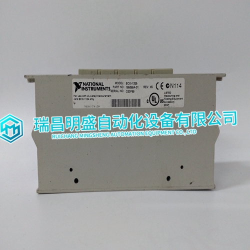
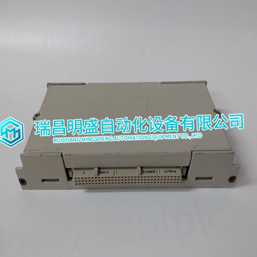
- Product ID: SCXI-1325
- Brand: NI
- Place of origin: the United States
- Goods status: new/used
- Delivery date: stock
- The quality assurance period: 365 days
- Phone/WhatsApp/WeChat:+86 15270269218
- Email:stodcdcs@gmail.com
- Tags:NISCXI-1325Voltage dc module
- Get the latest price:Click to consult
NI SCXI-1325 Voltage dc module
For TU or TM devices, connect the hooded end of the termination cable from the TU or TM to the MMU backplane. To do this, insert the connector into the backplane slot in the same slot as the one assigned to the digital output module. The latches should snap securely into place. 4. Align the digital output module with the guide rails in the MMU; gently slide the module in until the front panel is flush with the top and bottom of the MMU frame. 5. Push and turn the two captive retaining screws on the module faceplate one half turn to the latched position. It is latched when the slots on the screws are vertical and the open ends face the center of the module.
Termination Configuration
A termination unit (TU) or termination module (TM) connects the field device wiring to the INFI 90 OPEN system. The terminal blocks (connection points) are located on the TU or TM. Configuration of the TU or TM is required to accept the digital field inputs sent to the DSI module. Refer to the appendices at the back of this instruction manual for complete information.NOTE: This installation section provides instructions pertaining to the physical installation of the digital output module only. For complete cable and termination information, refer to the applicable instruction manual (Table 1-2). The DSO module inserts into a standard INFI 90 OPEN module mounting unit (MMU) and occupies one slot. To install: 1. Verify the slot assignment of the module. 2. Verify that a dipshunt is in the I/O expander bus socket on the MMU backplane between the I/O module and control module.
WIRING CONNECTIONS AND CABLING
The DSO has three card edge connectors to supply logic power, establish I/O expander bus communication and provide digital outputs (P1, P2, P3 respectively). Wiring Installing the module in the MMU connects the digital output module to the logic power (+5 VDC), necessary to drive the circuitry, at P1. It also connects P2 to the I/O expander bus for communication with the control module. P1 and P2 connections require no additional wiring or cabling. NOTE: You must install a dipshunt on the backplane of the MMU to connect the I/O expander bus between the digital output module and the control module. Locate the modules so the bus can connect the modules or they will not communicate.
The main products
Spare parts spare parts, the DCS control system of PLC system and the robot system spare parts,
Brand advantage: Allen Bradley, BentlyNevada, ABB, Emerson Ovation, Honeywell DCS, Rockwell ICS Triplex, FOXBORO, Schneider PLC, GE Fanuc, Motorola, HIMA, TRICONEX, Prosoft etc. Various kinds of imported industrial parts
Products are widely used in metallurgy, petroleum, glass, aluminum manufacturing, petrochemical industry, coal mine, papermaking, printing, textile printing and dyeing, machinery, electronics, automobile manufacturing, tobacco, plastics machinery, electric power, water conservancy, water treatment/environmental protection, municipal engineering, boiler heating, energy, power transmission and distribution and so on.