Home > Product > DCS control system > SIOC086406-002 Output module
SIOC086406-002 Output module
- Product ID: SIOC086406-002
- Brand: ABB
- Place of origin: The Swiss
- Goods status: new/used
- Delivery date: stock
- The quality assurance period: 365 days
- Phone/WhatsApp/WeChat:+86 15270269218
- Email:xiamen2018@foxmail.com
- Tags:SIOC086406-002Output module
- Get the latest price:Click to consult
SIOC086406-002 Output module
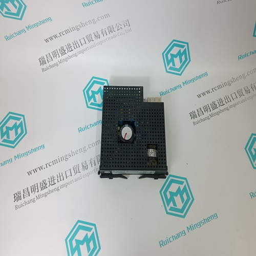
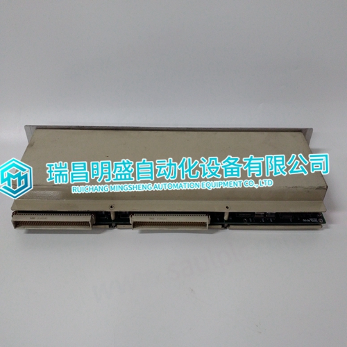
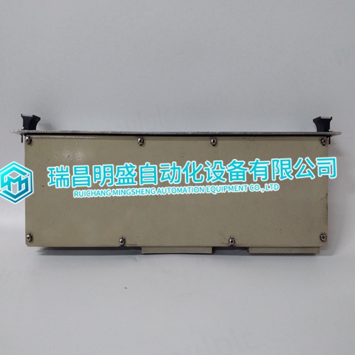
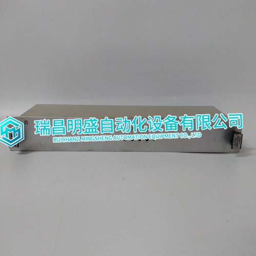
The IMDSO14 digital output module can use either a NTDI01 or NTDO02 termination unit or a NIDI01 termination module for termination. Refer to Figure 3-3 to determine the cables to use with the NTDI01 and the NIDI01. Refer to Figure 3-4 to determine cables to use with the NTDO02 termination unit.The IMDSO14 digital output module does not have any on board fusing requirements. PREOPERATING ADJUSTMENTS The IMDSO14 digital output module does not require any adjustments prior to operation.This section explains the front panel indicators and start-up procedures for the IMDSO14 Digital Output module. STATUS INDICATORS The DSO module has two front panel module status LED indicators to aid in system test and diagnosis. Sixteen front panel indicators display the output states (ON or OFF). The location of the indicators is shown in Figure 4-1.Table 4-1 describes the states of the module status LED indicators (refer to TROUBLESHOOTING in Section 5 to determine corrective actions).
Output Status Indicators
There are 16 front panel indicators (group A and group B) to display the output states. Each indicator represents one digital output. A red LED indicates an energized (ON) output; a blank LED indicates a non-energized (OFF) output. START-UP PROCEDURES The control module controls the start-up of the DSO module; it is fully automatic. Function Code (FC) 83 in the control module configuration enables the DSO. Specification S1 (FC 83) is the module address. It must be the same as the address set on the module S1 address dipswitch. The front panel LEDs (green solid, red off) verifies that the module is enabled and communicating.This section explains the error indications and corrective actions for the IMDSO14 Digital Output (DSO) module
ERROR INDICATIONS AND CORRECTIVE ACTION
You can obtain the status of the DSO module through an INFI 90 OPEN operator interface (e.g., Operator Interface Station, Engineering Work Station, Configuration and Tuning Terminal) or the front panel status LED indicators. NOTE: If you look at the DSO module front panel output status LED indicators and none are lit, this may indicate a faulty DSO (an output must be energized to light an LED). Check the control module for bad quality on its output blocks. Module Status LEDs The two front panel status LEDs have three states to indicate normal operation and error conditions. Table 5-1 lists DSO status LED states, error indications, probable causes and corrective actions. NOTE: If the corrective actions in Table 5-1 do not correct a problem with the DSO module, replace it.
The main products
Spare parts spare parts, the DCS control system of PLC system and the robot system spare parts,
Brand advantage: Allen Bradley, BentlyNevada, ABB, Emerson Ovation, Honeywell DCS, Rockwell ICS Triplex, FOXBORO, Schneider PLC, GE Fanuc, Motorola, HIMA, TRICONEX, Prosoft etc. Various kinds of imported industrial parts
Products are widely used in metallurgy, petroleum, glass, aluminum manufacturing, petrochemical industry, coal mine, papermaking, printing, textile printing and dyeing, machinery, electronics, automobile manufacturing, tobacco, plastics machinery, electric power, water conservancy, water treatment/environmental protection, municipal engineering, boiler heating, energy, power transmission and distribution and so on.