Home > Product > Gas turbine system > IC698CPE040 Gas turbine electrical module
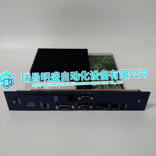
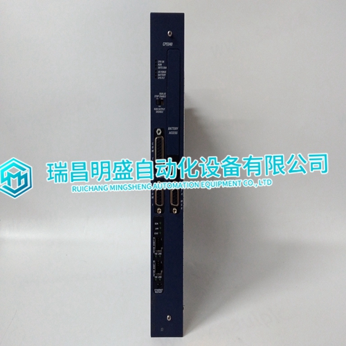
IC698CPE040 Gas turbine electrical module
- Product ID: IC698CPE040
- Brand: GE
- Place of origin: the United States
- Goods status: new/used
- Delivery date: stock
- The quality assurance period: 365 days
- Phone/WhatsApp/WeChat:+86 15270269218
- Email:stodcdcs@gmail.com
- Tags:IC698CPE040Gas turbine electrical module
- Get the latest price:Click to consult
IC698CPE040 Gas turbine electrical module
The IMDSO14 digital output module can use a NIDI01 termination module for termination. Jumpers on the termination module configure the digital outputs that are sent to the process. The DSO module outputs switch voltages of 24 VDC at 250 milliamps or 48 VDC at 125 milliamps. Refer to Table B-1 to determine the jumper setting to configure your application. Figure B-1 shows the terminal assignments for the digital output signals. Refer to this figure when connecting field wiring to the NIDI01. Refer to the NIDI01 instruction manual (Table 1-2) for complete termination module information.Normally each I/O module output controls one relay on the termination unit. The IMDSO14 I/O module has 16 outputs divided into two groups. Outputs one through eight belong to group A and outputs nine through 16 belong to group B. Group A controls outputs one through eight on a termination unit connected to the I/O module
The IMDSO14 digital output module
can use a NTDO02 for termination. The termination unit can provide up to eight solid state relay outputs. Dipshunts on the termination unit configure the I/O. Figure C-1 shows the NTDO02 configuration sockets (dipshunts). Refer to this figure when connecting field wiring to the NTDO02 termination unit. Refer to Tables C-1 and C-2 to determine the dipshunt strapping. Refer to the NTDO02 instruction manual (Table 1-2) for complete termination unit information.The termination unit can be interconnected to a second termination unit. Group B controls the second termination unit. Table C-1 shows the settings for dipshunts XU01 and XU02 for normal operation.
NOTE: To control the termination unit using I/O module group A (one through eight) outputs, install dipshunt XU01. To control the termination unit using I/O module group B (nine through 16) outputs, install dipshunt XU02. Do not install both dipshunts (XU01 and XU02) on the same termination unit.
Dipshunt Configuration
There are ten dipshunts on the termination unit. Figure C-1 shows the locations of the dipshunts. Dipshunts XU01 and XU02 determine the I/O module relay control. Configure a dipshunt by either cutting straps or leaving straps uncut in certain sequences. Cut the dipshunt straps using a standard shunt cutting tool. Always cut straps completely. Install the configured dipshunt into the desired socket on the termination unit. To install a dipshunt, align the end of the dipshunt identified with the silver dot to the end of the socket having an identification mark and push the dipshunt into the socket. Be careful not to bend any pins during insertion.
The main products
Spare parts spare parts, the DCS control system of PLC system and the robot system spare parts,
Brand advantage: Allen Bradley, BentlyNevada, ABB, Emerson Ovation, Honeywell DCS, Rockwell ICS Triplex, FOXBORO, Schneider PLC, GE Fanuc, Motorola, HIMA, TRICONEX, Prosoft etc. Various kinds of imported industrial parts
Products are widely used in metallurgy, petroleum, glass, aluminum manufacturing, petrochemical industry, coal mine, papermaking, printing, textile printing and dyeing, machinery, electronics, automobile manufacturing, tobacco, plastics machinery, electric power, water conservancy, water treatment/environmental protection, municipal engineering, boiler heating, energy, power transmission and distribution and so on.