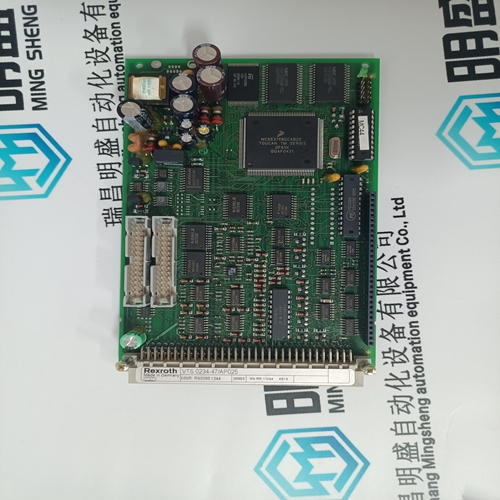
Home > Product > DCS control system > SR511 3BSE000863R1 industrial module
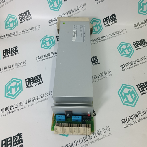
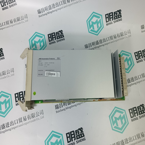
SR511 3BSE000863R1 industrial module
- Product ID: SR511 3BSE000863R1
- Brand: ABB
- Place of origin: The Swiss
- Goods status: new/used
- Delivery date: stock
- The quality assurance period: 365 days
- Phone/WhatsApp/WeChat:+86 15270269218
- Email:stodcdcs@gmail.com
- Tags:SR511 3BSE000863R1industrial module
- Get the latest price:Click to consult
The main products
Spare parts spare parts, the DCS control system of PLC system and the robot system spare parts,
Brand advantage: Allen Bradley, BentlyNevada, ABB, Emerson Ovation, Honeywell DCS, Rockwell ICS Triplex, FOXBORO, Schneider PLC, GE Fanuc, Motorola, HIMA, TRICONEX, Prosoft etc. Various kinds of imported industrial parts
SR511 3BSE000863R1 industrial module
When the input 'AdjRErInp' is enabled, the error code 133.00 is displayed initially until the resistance has been computed. This can take a maximum of 10 s after which the value measured for REr is displayed. The value measured for Rf is 97.0. During normal operation, the value entered for REr on the HMI is displayed. Normal operation: Neither of the two I/P's 'AdjCoupCInp' and 'AdjRErInp' are disabled and injection is taking place. Note: Only one of the binary I/P's may be enabled at any one time, otherwise an error code is generated for the measurements Rf, C and REr (see table below).
The normal rotor injection voltage is 50 V. Provision is also made for an injection voltage of 20 or 30 V by appropriately changing the wiring on the injection transformer block Type REX 011.BlockInp Binary address used as blocking input. (FFALSE, TTRUE, binary input or output of a protection function). Trip Output for signalling tripping. StartTrip Output for signalling the pick-up of the tripping stage. Alarm Output for signalling an alarm. StartAlarm Output for signalling the pick-up of the alarm stage.
InterruptInt Output
for signalling an open-circuit injection circuit. InterruptExt. Output for signalling an open-circuit measuring circuit. This signal address has a pick-up and a rest delay of each 5s. REr-Adjust Output for signalling the binary status of 'AdjRErInp'. (signal address) CoupC-Adjust Output for signalling the binary status of 'AdjCoupCInp'. Extern-Block Output for signalling that the function is disabled by an external signal. (signal address) Note: If stator and rotor ground fault protection schemes are in use, the same analogue channel Ui must be selected for both.
E. Setting instructions The value of 'RFr- Setting' for alarm must always be greater than that of 'RFr- Setting' for tripping. Both alarm and tripping stages have their own timers. Typical delays used for the rotor ground fault protection are in the range of seconds. Recommended resistances: REr = 1000 RPr = 100 Settings: Grounding resistor REr Coupling capacitor C 'RFr- Setting' for tripping 'RFr- Setting' for alarm Delay for alarm Delay for tripping Typical settings: Alarm stage: RFr- Setting 5 k delay 2 s Tripping stage: RFr- Setting 500 delay 1 s. Setting procedure: How accurately Rfr is measured depends on the values entered for REr and C. Therefore check the settings and correct them if necessary by connecting resistors between 100 and 10 k between the rotor and ground with the generator at a stand still. The protection function provides a convenient way of setting these two parameters in the software by switching its mode using the input 'AdjRErInp' or 'AdjCoupCInp'. In this mode, the settings of the parameters 'REr' and 'C' are calculated with the aid of simulated ground fault resistances.
