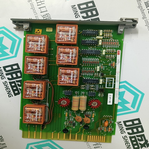
Home > Product > Gas turbine system > 8851-LC-MT Gas turbine electric card
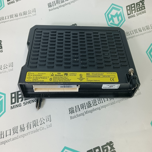
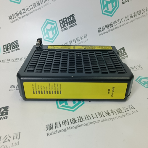
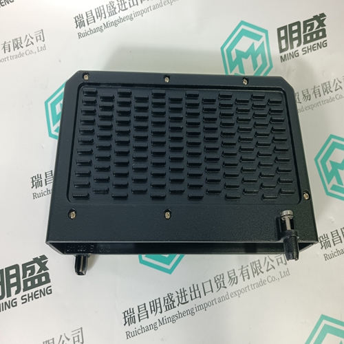
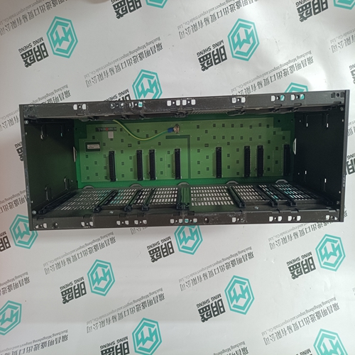
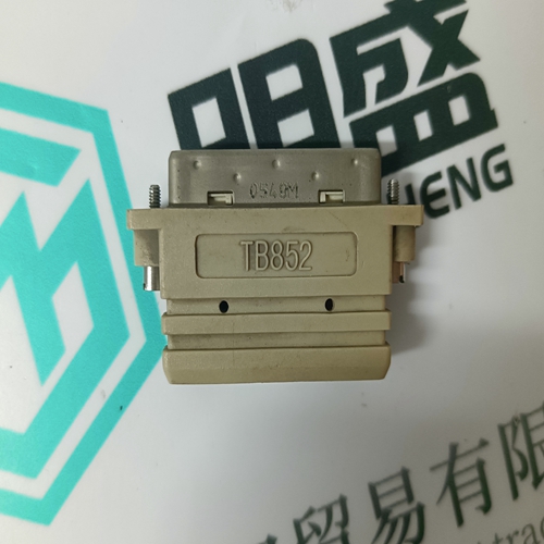
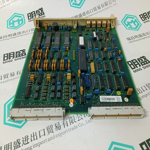
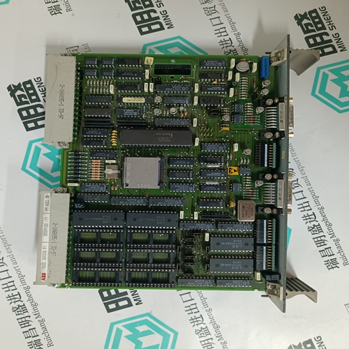
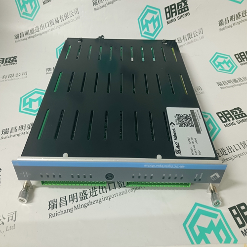
8851-LC-MT Gas turbine electric card
- Product ID: 8851-LC-MT
- Brand: GE
- Place of origin: the United States
- Goods status: new/used
- Delivery date: stock
- The quality assurance period: 365 days
- Phone/WhatsApp/WeChat:+86 15270269218
- Email:stodcdcs@gmail.com
- Tags:8851-LC-MTGas turbine electric card
- Get the latest price:Click to consult
The main products
Spare parts spare parts, the DCS control system of PLC system and the robot system spare parts,
Brand advantage: Allen Bradley, BentlyNevada, ABB, Emerson Ovation, Honeywell DCS, Rockwell ICS Triplex, FOXBORO, Schneider PLC, GE Fanuc, Motorola, HIMA, TRICONEX, Prosoft etc. Various kinds of imported industrial parts
8851-LC-MT Gas turbine electric card
Settings: Current and voltage inputs A three-phase group must be used for the current input. The following can be set for the voltage input: single-phase input using URS three-phase delta group three-phase star group. The sampling group of the current angle voltage inputs must also be taken into account. There are no restrictions on Phi providing the current input number is lower than the voltage input number and we urgently recommend observing this rule when connecting the protection.Setting: Phi The angle Phi determines the angle of the slip line and is monitored to detect slip. The impedances ZA, ZB and ZC lie on this line.Setting: ZA ZA is the impedance of the slip line and marks the limit of zone 2. It is also used for measuring phase-angle (see 'WarnAngle' and 'TripAngle'). ZA should be set to the impedance between the location of the protection and the off-load voltage of the equivalent circuit for the entire power system. Setting: ZB ZB is the impedance of the slip line in the reverse direction and marks the limit of zone 1. It is also used for measuring phaseangle (see 'WarnAngle' and 'TripAngle'). ZB should be set to the generator reactance X'd in the reverse direction (negative sign). Setting: ZC ZC divides the slip line into two zones. Zone 1 lies between ZB and ZC and zone 2 between ZC and ZA. ZC should be set to the impedance from the location of the protection up to the first busbar
Setting: WarnAngle
The rotor angle is given by the triangle bounded by the instantaneous impedance and the impedances ZA and ZB. The protection, however, measures the angle between the instantaneous voltage and the rotor voltages EA and EB, which closely approximates the impedance triangle.
The rotor angle is given by the triangle bounded by the instantaneous impedance and the impedances ZA and ZB. The protection, however, measures the angle between the instantaneous voltage and the rotor voltages EA and EB, which closely approximates the impedance triangle.
The setting for 'WarnAngle' can be set between 0° and 180° and determines the rotor angle above which alarm of imminent slipping is given. With setting of 'WarnAngle' = 0°, alarm is given immediately the rotor angle changes, providing it lies within the pick-up range. 'WarnAngle' enables the operating status of the generator to be corrected, because its rotor angle setting is reached before the first slip. The machine can normally be stabilised for rotor angles up to 135°, for example, by changing the excitation or switching in compensators. For a setting of 'WarnAngle' = 180°, alarm is not given until the first slip takes place, i.e. at the same time as the signal for zone 1 or zone 2. Typical setting: WarnAngle = 110°.
