Home > Product > Gas turbine system > DS200TCCAG1BAA Gas turbine electrical module
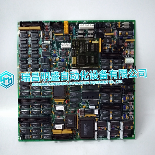
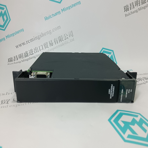
DS200TCCAG1BAA Gas turbine electrical module
- Product ID: DS200TCCAG1BAA
- Brand: GE
- Place of origin: The United States
- Goods status: new/used
- Delivery date: stock
- The quality assurance period: 365 days
- Phone/WhatsApp/WeChat:+86 15270269218
- Email:stodcdcs@gmail.com
- Tags:DS200TCCAG1BAAGas turbine electrical module
- Get the latest price:Click to consult
DS200TCCAG1BAA Gas turbine electrical module
Event Location Message transfer is, as mentioned earlier, performed in an event driven manner. Three different master frames are available to determine which communication interfaces want to send a packet. The event location is performed in a series of rounds. In each round, every communication interface is given the opportunity of sending a packet (see Message Transfer on page 285).The address/control field specifies some general parameters for the event location. The event mode field (4 bits) specifies whether a new round may begin, and whether an answer is expected at all. The event type field (4 bits) specifies the type of event (message transfer or process data). Event driven transmission of process data is currently not used in the Advant Fieldbus 100 network. When a new round begins, all communication interfaces may answer if they want to send a packet. If more than one communication interface answers such a master frame, the result will be a collision on the bus. This situation can be detected by the bus master, however, it can not obtain the answer from any of the answering communication interfaces.
Searching for Communication Interfaces
In case of a collision the bus master now employs function code 13 and 14 to search for the communication interfaces that want to send something. Both these frames contain a pattern in the address/ control field, which only allows a part of the communication interfaces to answer.The next master frame it sends allows only half of the communication interfaces to answer. In case of another collision, the number of communication interfaces that may answer is again halved, etc. If, during this search procedure, no answer is received, the bus master just switches to the other half and continues from there. The event location algorithm can be depicted as a search down a binary tree.
For an example, see Figure 114 below where the search tree for a configuration with 16 communication interfaces is depicted. The dots on the bottom line represent the communication interfaces. Two communication interfaces desiring to send a packet are indicated with an arrow. At point 1 (the root of the search tree) the new round is begun. Here a collision is detected, that is at least two stations have data to send. The bus master transfers to point 2 in the tree and uses function codes 13 and 14 to search for a communication interface which wants to send a packet. Only the communication interfaces attached to the sub-tree below point 2 may answer.
