Home > Product > DCS control system > FBM223 P0917HD Input module
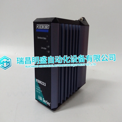
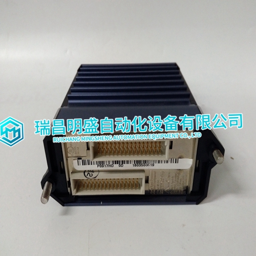
FBM223 P0917HD Input module
- Product ID: FBM223 P0917HD
- Brand: FOXBORO
- Place of origin: The United States
- Goods status: new/used
- Delivery date: stock
- The quality assurance period: 365 days
- Phone/WhatsApp/WeChat:+86 15270269218
- Email:stodcdcs@gmail.com
- Tags:FBM223P0917HDInput module
- Get the latest price:Click to consult
FBM223 P0917HD Input module
Use an Antistatic Field Service Vacuum. Remove dust from the modules if necessary. Use a Grounded Wrist Strap. Connect the wrist strap to the appropriate grounding plug on the power entry panel. The grounding plug is connected to the cabinet chassis ground.Do Not Use Lead Pencils to Set Dipswitches. To avoid contamination of switch contacts that can result in circuit board malfunction, do not use a lead pencil to set a dipswitch For the IMFEC12 module, there is one dipswitch (S1, Fig. 3-1 is the same for both the IMFEC11 and the IMFEC12) that must be set before installing the module. The single dipswitch sets the I/O expander bus address. For the IMFEC11 module, there is one dipswitch (S1) and 18 jumpers (J2-J4 and J6 -J20) that must be set before installing the module (Fig. 3-1). The single dipswitch sets the I/O expander bus address. Jumpers J2 through J4 set the operating and communication mode, and jumpers J6 through J20 select the input (voltage/current).
UNPACKING AND INSPECTION
For general handling: 1. Examine the module to make sure that no damage has occurred in transit. 2. Notify the nearest Elsag Bailey sales office of any damage. 3. File a claim for any damage with the shipping company that handled the shipment. 4. Use the original packing material to store the module. 5. Store the module in a place with clean air, free from extremes of temperature and humidity. Refer to Table 1-5 for the module specifications.NOTE: Input jumpers (J6 through J20) must be set to the voltage position (Fig. 3-1) when using a NTAI05 termination unit, a NIAI04 termination module or the NTFB01 field bus termination unit.
INSTALLATION IN HAZARDOUS LOCATIONS
One or more intrinsic safety barriers are required when the FEC module interfaces to transmitters or other external devices located in a Division I hazardous location (flammable atmosphere). Refer to the Installing a 4 to 20 mA Transmitter in a Hazardous Location application guide (Table 1-2) to determine the intrinsic safety barrier requirements for your application.Full FEC functionality requires the use of enhanced versions of function codes 132 and 133. The module firmware revision levels listed in Table 3-1 support the enhanced function codes.