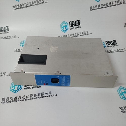
Home > Product > Gas turbine system > IS200STCIH6AED Combustion engine general card
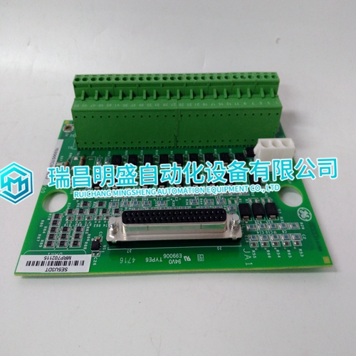
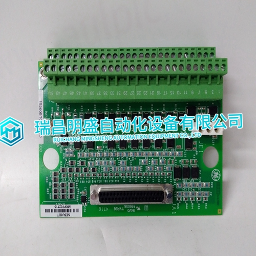
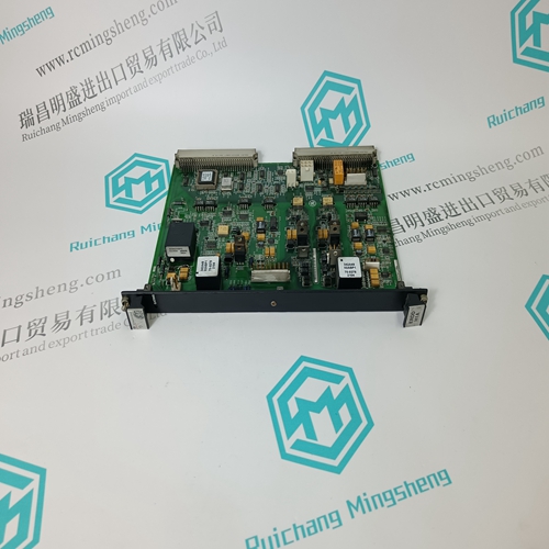
IS200STCIH6AED Combustion engine general card
- Product ID: IS200STCIH6AED
- Brand: GE
- Place of origin: The United States
- Goods status: new/used
- Delivery date: stock
- The quality assurance period: 365 days
- Phone/WhatsApp/WeChat:+86 15270269218
- Email:stodcdcs@gmail.com
- Tags:IS200STCIH6AEDCombustion engine general card
- Get the latest price:Click to consult
IS200STCIH6AED Combustion engine general card
The FEC module must have a unique address on the I/O expander bus. The FEC module can have one of 64 addresses (zero to 63). This address identifies the FEC module to the control module and must be the same as the address set in the control module setup data (function code 132, specification S1). Set the address with the eight-position address dipswitch (S1) shown in Figure 3-1. Switch positions three through eight of S1 set the six-bit address. Positions one and two must remain in the closed position. Refer to Table 3-2 for examples of address settings. Record the I/O expander bus address of the FEC module in the space provided.
Factory Test Jumper (J2)
Jumper J2 is used for factory test purposes only. When in the ON position, this jumper enables an LCD display that connects to J1 for diagnostic purposes. This is a factory test feature and should always be disabled (OFF) during normal operation. If this jumper is in the ON position during normal operation, it degrades the operation of the module because of the extra time required to run diagnostics. Table 3-3 shows the setting for J2.The operating mode jumper sets the IMFEC11 operation to point-to-point mode or field bus mode. Set jumper J3 for the desired operating mode. Table 3-3 lists the jumper settings.
IMFEC11 Communication Mode Jumper (J4)
The communication mode jumper sets the IMFEC11 communication mode. Table 3-3 lists the jumper setting for J4. Refer to Figure 3-1 for the location of J4 on the FEC circuit board. IMFEC11 Input Jumpers (J6 through J20) Fifteen input jumpers allow selection of voltage or current inputs. Refer to Table 3-3 for jumper descriptions. Figure 3-1 shows the location of the input jumpers and also a diagram silkscreened on the board that shows how to position the jumper. Each jumper has a left pin, center pin and right pin. For voltage, position the jumper on the left and center pins. For current, the jumper would be on the center and right pins.

