Home > Product > DCS control system > PM861K01 3BSE018105R1 Control module
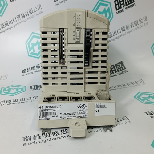
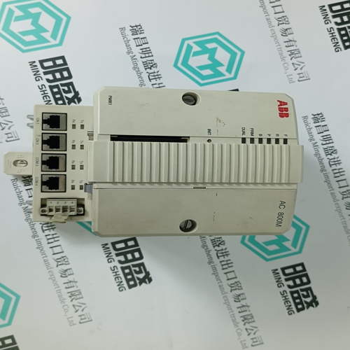
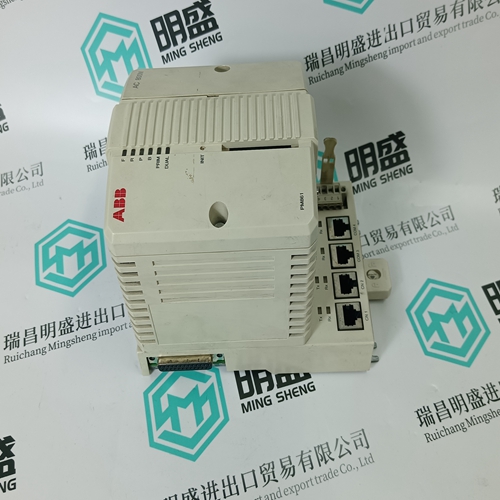
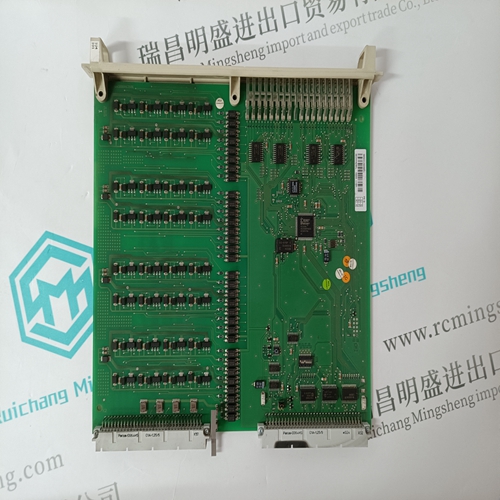
PM861K01 3BSE018105R1 Control module
- Product ID: PM861K01 3BSE018105R1
- Brand: ABB
- Place of origin: The Swiss
- Goods status: new/used
- Delivery date: stock
- The quality assurance period: 365 days
- Phone/WhatsApp/WeChat:+86 15270269218
- Email:stodcdcs@gmail.com
- Tags:PM861K01 3BSE018105R1Control module
- Get the latest price:Click to consult
The main products
Spare parts spare parts, the DCS control system of PLC system and the robot system spare parts,
Brand advantage: Allen Bradley, BentlyNevada, ABB, Emerson Ovation, Honeywell DCS, Rockwell ICS Triplex, FOXBORO, Schneider PLC, GE Fanuc, Motorola, HIMA, TRICONEX, Prosoft etc. Various kinds of imported industrial parts
PM861K01 3BSE018105R1 Control module
A power relay is installed at both ends of every line with the exception of stub lines, which only require a relay at the source end. If the E/F current is too low and has to be artificially increased, an overvoltage relay is fitted to detect the displacement voltage and connect a grounding resistor temporarily to the starpoint. To avoid any incorrect response of the power relays while this is being done, they are enabled after a short delay. The section of the line with the fault is determined by comparison of the relay directions. The real power component of the E/F current is determined by the resistive losses of the lines, the Petersen coils and the grounding resistors. A typical value for the charging current of overhead lines is around 2.5 A / 10 kV and 100 km. In the case of cable systems, it can be determined from the cable data. The minimum real power component of the current at the minimum voltage at which the power relay has to operate can be determined according to the above procedure. The power at which it must pick up must be set somewhat lower to allow for phase and ratio errors of the c.t's. The parameter ‘Angle’ must be set to 0° to measure real power in the forwards direction, respectively 180° to measure real power in the reverse direction. Note: The connections are made in strict accordance with the ABB wiring diagram.
Example of how to determine the setting
Assuming an overhead line system with an E/F current (sum of the three phase currents) of 30 A and a real power current component of 5 A. The core-balance c.t. has a ratio of 125:1. The star-point v.t. has a secondary voltage of 100 V for a solid E/F at the generator/power transformer terminals. Therefore: PN = 1 A x 100 V = 100 VA. It is required to detect E/F's down to 50 % of the displacement voltage. The E/F current flows only from one side, so that no division of the current takes place. The real power component of the current of 5 A results in a secondary current of: IW = 5 A x 1/125 = 0.04 A at maximum displacement voltage IW = 0.04 A x 0.5 = 0.02 A at 50 % displacement voltage
The required pick-up power is thus: P = 0.02 A x 50 V = 1 VA This corresponds to 1 % referred to the rated power PN of 100 VA. A setting of 0.5 % PN is possible, but the accuracy of the c.t's must be checked before deciding whether such a sensitive setting is permissible. The real power can be increased by adding a grounding resistor.
