Home > Product > DCS control system > LT9673a HESG446076R1 HE663599-31813 module
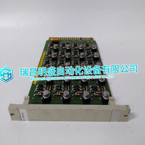
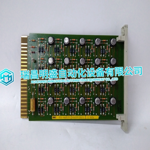
LT9673a HESG446076R1 HE663599-31813 module
- Product ID: LT9673a HESG446076R1 HE663599-31813
- Brand: ABB
- Place of origin: The Swiss
- Goods status: new/used
- Delivery date: stock
- The quality assurance period: 365 days
- Phone/WhatsApp/WeChat:+86 15270269218
- Email:stodcdcs@gmail.com
- Tags:LT9673aHESG446076R1HE663599-31813module
- Get the latest price:Click to consult
LT9673a HESG446076R1 HE663599-31813 module
Verify all the connections on the module. Check that • the Modbus cable is connected correctly to terminal block X2. • 24 V d.c. power is connected to the power connectors. • the fibre cables between the drive and the NMBA-01 are correctly connected. • the fibre link connector colours match the drive and NMBA-01 connector colours. Drive Setup Fieldbus parameter group is not visible on the control panel. • Activate the fieldbus module according to the instructions in the drive manual. Drive parameters can be read, but control commands (Start/Stop or Reference) do not work. • Check that the drive has the fieldbus adapter selected as the source of these commands (see the drive manual).
PLC Programming
PLC program is beyond ABB support. Contact the manufacturer for assistance.The NMBA-01 has three status LEDs. These are from top to bottom: • XMIT LED. This LED will flash each time the NMBA-01 transmits a response or an exception on the Modbus network. • REC LED. This LED will flash each time the NMBA-01 receives a command from the Modbus network. • ERROR LED for combined error and module status indication. This LED will flash for the following reasons: - If the received command had a parity error. - If the received command had a CRC error. - If the received command was not supported by the NMBA-01 module. In this case the XMIT LED will also flash. - If the NMBA-01 module has found an error. The error codes are described in Table 7-2 below.
Module Diagnostics
On module power-up, the NMBA-01 goes through a power-up self-test sequence. During this, the test state is indicated by the front three LEDs. The normal power-up procedure is as follows: • All LEDs are turned on for the duration of the RAM/ROM test. If the test is passed, all LEDs will be turned off. • The ERROR LED will flash rapidly for few seconds as the DDCS link between the NMBA-01 and the drive is initialised. • REC and XMIT LEDs will flash according to the data transferred between the NMBA-01 and the drive.