Home > Product > PLC programmable module > NI PXI-4071 Voltage dc module
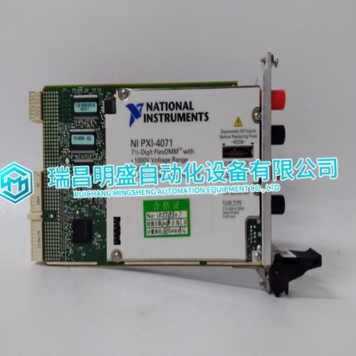
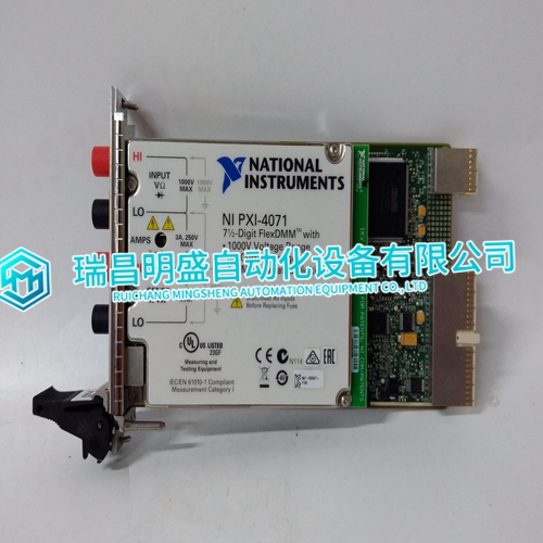
NI PXI-4071 Voltage dc module
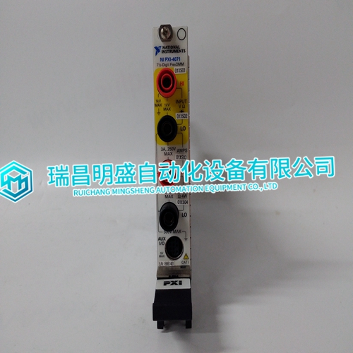
- Product ID: PXI-4071
- Brand: NI
- Place of origin: The United States
- Goods status: new/used
- Delivery date: stock
- The quality assurance period: 365 days
- Phone/WhatsApp/WeChat:+86 15270269218
- Email:stodcdcs@gmail.com
- Tags:NIPXI-4071Voltage dc module
- Get the latest price:Click to consult
NI PXI-4071 Voltage dc module
This chapter describes the serial Modbus protocol. This chapter is intended for people who need to program a serial Modbus master for their own control system. The material of this chapter is copyrighted by Modicon, and is used by permission of AEG Schneider Automation (Modicon). This material is included in the Modicon publication Modicon Modbus Protocol Reference Guide (PI-MBUS-300 Rev. E).The Modbus protocol is a serial master–slave protocol. This appendix describes the Modbus protocol only to the level which is required to fully access the ABB drives. The Modbus protocol defines what is serially transmitted on the communication link. The physical interface to the NMBA-01 is half-duplex RS-485.
Transactions on Modbus Networks
Standard Modbus ports on Modicon controllers use an RS-232C compatible serial interface that defines connector pinouts, cabling, signal levels, transmission baud rates, and parity checking. Controllers can be networked directly or via modems. Controllers communicate using a master – slave technique, in which only one device (the master) can initiate transactions (called ‘queries’). The other devices (the slaves) respond by supplying the requested data to the master, or by taking the action requested in the query. Typical master devices include host processors and programming panels. Typical slaves include programmable controllers. The master can address individual slaves, or can initiate a broadcast message to all slaves. Slaves return a message (called a ‘response’) to queries that are addressed to them individually. Responses are not returned to broadcast queries from the master.
Modbus Protocol
The Modbus protocol establishes the format for the master’s query by placing into it the device (or broadcast) address, a function code defining the requested action, any data to be sent, and an error-checking field. The slave’s response message is also constructed using Modbus protocol. It contains fields confirming the action taken, any data to be returned, and an error-checking field. If an error occurred in receipt of the message, or if the slave is unable to perform the requested action, the slave will construct an error message and send it as its response.