Home > Product > DCS control system > SA9923a-E HIEE450964R0001 Logic input module
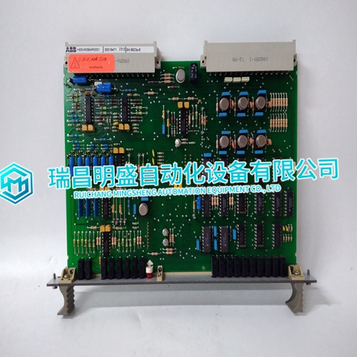
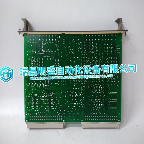
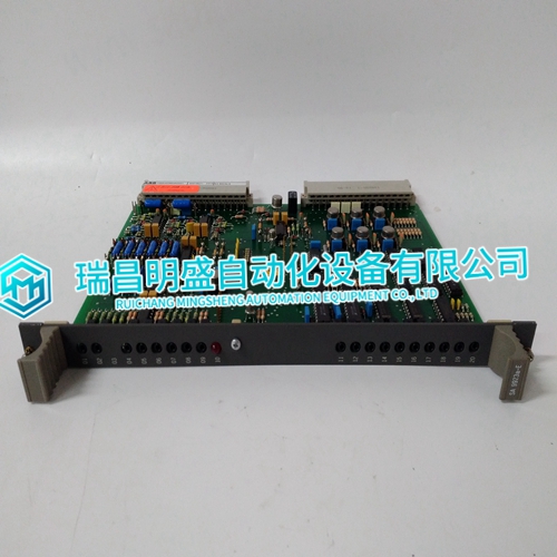
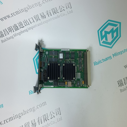
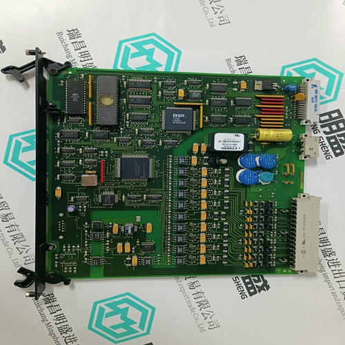
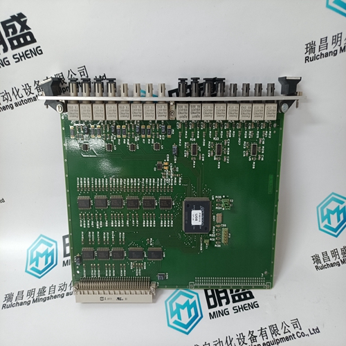
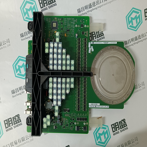
SA9923a-E HIEE450964R0001 Logic input module
- Product ID: SA9923a-E HIEE450964R0001
- Brand: ABB
- Place of origin: The Swiss
- Goods status: new/used
- Delivery date: stock
- The quality assurance period: 365 days
- Phone/WhatsApp/WeChat:+86 15270269218
- Email:stodcdcs@gmail.com
- Tags:SA9923a-EHIEE450964R0001Logic input module
- Get the latest price:Click to consult
SA9923a-E HIEE450964R0001 Logic input module
The Query: The function code in the query tells the addressed slave device what kind of action to perform. The data bytes contain any additional information that the slave will need to perform the function. For example, function code 03 will query the slave to read holding registers and respond with their contents. The data field must contain the information telling the slave which register to start at and how many registers to read. The error check field provides a method for the slave to validate the integrity of the message contents.
The Response: If the slave makes a normal response, the function code in the response is an echo of the function code in the query. The data bytes contain the data collected by the slave, such as register values or status. If an error occurs, the function code is modified to indicate that the response is an error response, and the data bytes contain a code that describes the error. The error check field allows the master to confirm that the message contents are valid.
The Two Serial Transmission Modes
Controllers can be setup to communicate on standard Modbus networks using either of two transmission modes: ASCII or RTU. Users select the desired mode, along with the serial port communication parameters (baud rate, parity mode, etc.), during configuration of each controller. The mode and serial parameters must be the same for all devices on a Modbus network. The selection of ASCII or RTU mode pertains only to standard Modbus networks. It defines the bit contents of message fields transmitted serially on those networks. It determines how information will be packed into the message fields and decoded. The NMBA-01 supports only the RTU mode. Only the RTU mode is described in this document.

