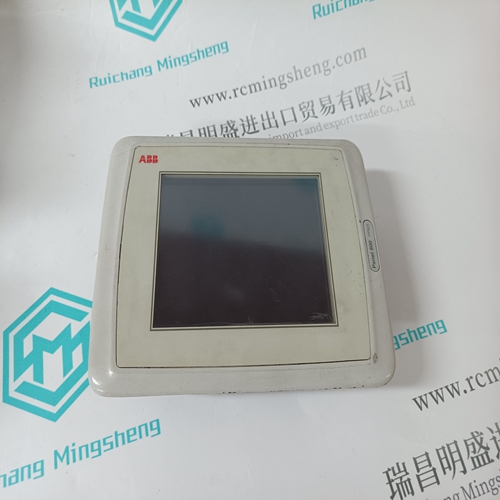
Home > Product > DCS control system > UAC326AE01 HIEE401481R1 Logic output module
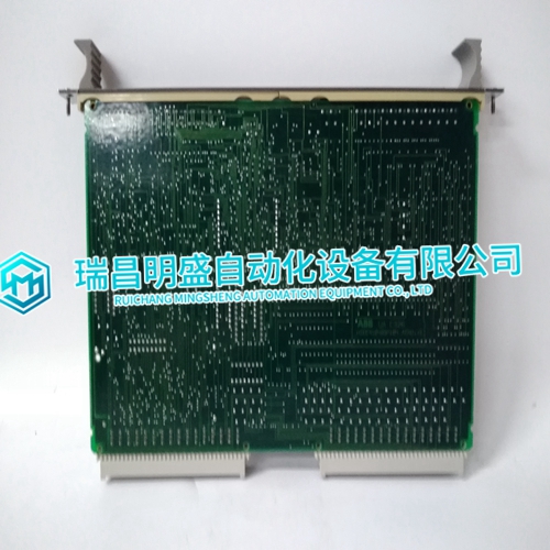
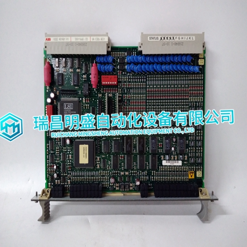
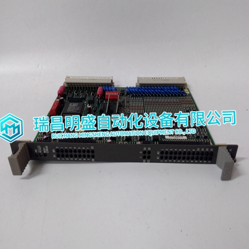
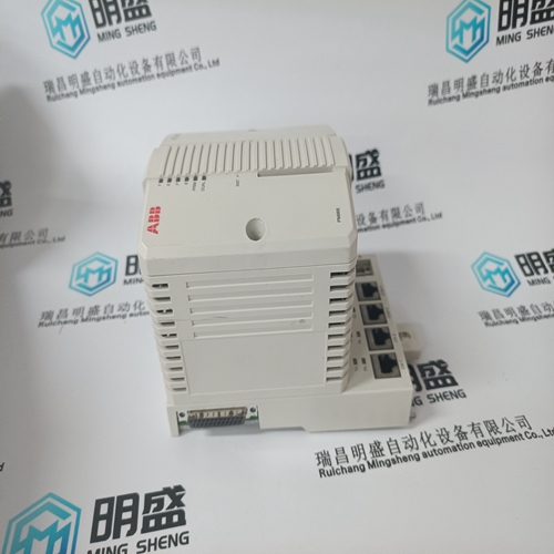
UAC326AE01 HIEE401481R1 Logic output module
- Product ID: UAC326AE01 HIEE401481R1
- Brand: ABB
- Place of origin: The Swiss
- Goods status: new/used
- Delivery date: stock
- The quality assurance period: 365 days
- Phone/WhatsApp/WeChat:+86 15270269218
- Email:stodcdcs@gmail.com
- Tags:UAC326AE01HIEE401481R1Logic output module
- Get the latest price:Click to consult
UAC326AE01 HIEE401481R1 Logic output module
In RTU mode, messages include an error-checking field that is based on a Cyclical Redundancy Check (CRC) method. The CRC field checks the contents of the entire message. It is applied regardless of any parity check method used for the individual characters of the message. The CRC field is two bytes, containing a 16-bit binary value. The CRC value is calculated by the transmitting device, which appends the CRC to the message. The receiving device recalculates a CRC during receipt of the message, and compares the calculated value to the actual value it received in the CRC field. If the two values are not equal, an error results. The CRC is started by first pre-loading a 16-bit register to all 1’s. Then a process begins of applying successive 8-bit bytes of the message to the current contents of the register. Only the eight bits of data in each character are used for generating the CRC. Start and stop bits, and the parity bit if one is used, do not apply to the CRC.
During generation of the CRC
each 8-bit character is exclusive ORed with the register contents. Then the result is shifted in the direction of the least significant bit (LSB), with a zero filled into the most significant bit (MSB) position. The LSB is extracted and examined. If the LSB was a 1, the register is then exclusive ORed with a preset, fixed value. If the LSB was a 0, no exclusive OR takes place. This process is repeated until eight shifts have been performed. After the last (eighth) shift, the next 8-bit byte is exclusive ORed with the register’s current value, and the process repeats for eight more shifts as described above. The final contents of the register, after all the bytes of the message have been applied, is the CRC value.
In ladder logic
the CKSM function calculates a CRC from the message contents. For applications using host computers, a detailed example of CRC generation is contained later in this appendix. Modbus Function Formats This chapter describes in detail the data content on every Modbus message supported by the NMBA-01.

