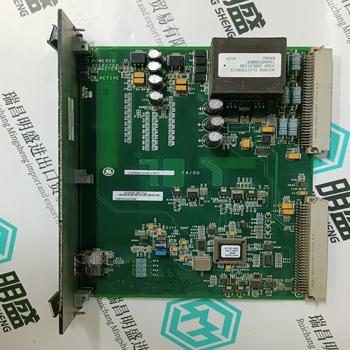
Home > Product > DCS control system > XV9738a HEIE450617R1 Voltage dc module
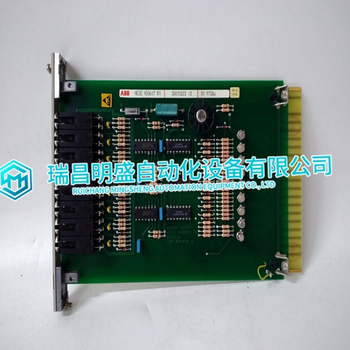
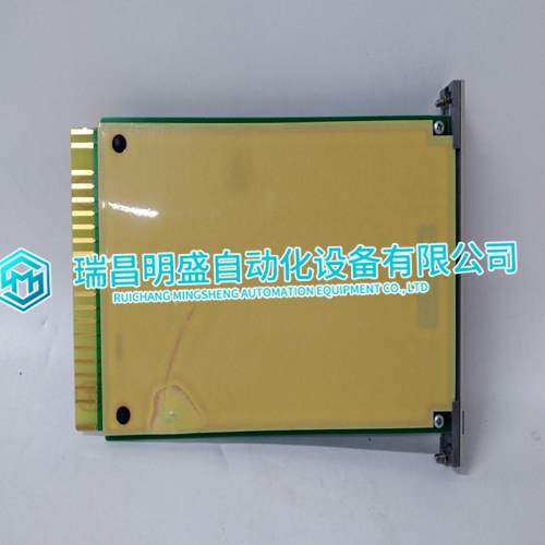
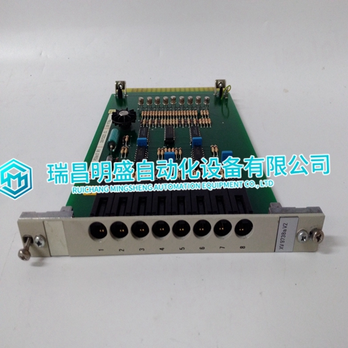
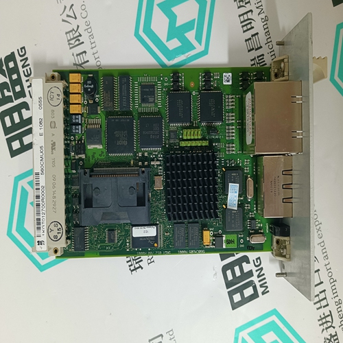
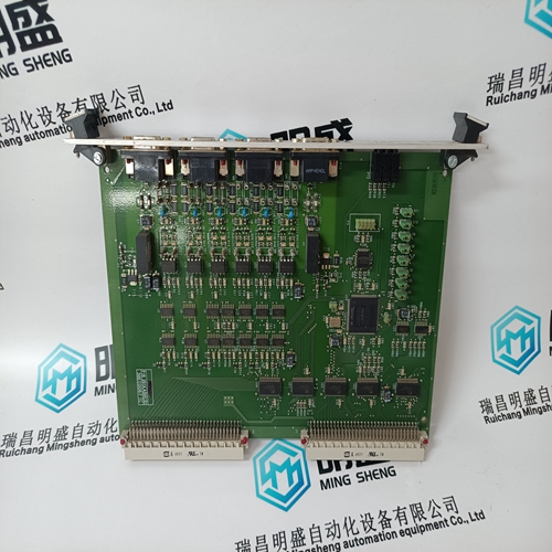
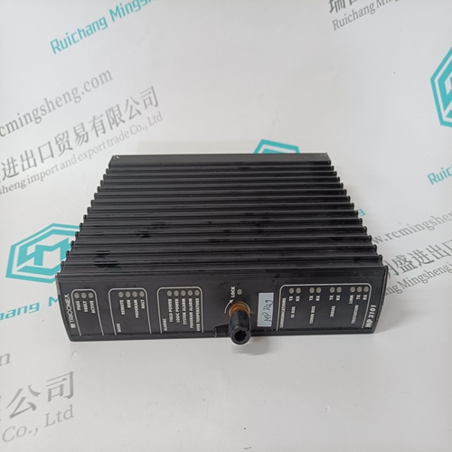
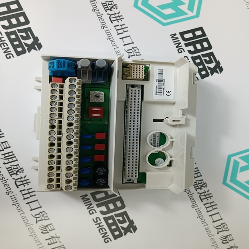
XV9738a HEIE450617R1 Voltage dc module
- Product ID: XV9738a HEIE450617R1
- Brand: ABB
- Place of origin: The Swiss
- Goods status: new/used
- Delivery date: stock
- The quality assurance period: 365 days
- Phone/WhatsApp/WeChat:+86 15270269218
- Email:stodcdcs@gmail.com
- Tags:XV9738aHEIE450617R1Voltage dc module
- Get the latest price:Click to consult
XV9738a HEIE450617R1 Voltage dc module
All data addresses in Modbus messages are referenced to zero. The first occurrence of a data item is addressed as item number zero. For example: • The coil known as ‘coil 1’ in a programmable controller is addressed as coil 0000 in the data address field of a Modbus message. • Coil 127 decimal is addressed as coil 007E hex (126 decimal). • Holding register 40001 is addressed as register 0000 in the data address field of the message. The function code field already specifies a ‘holding register’ operation. Therefore the ‘4XXXX’ reference is implicit. • Holding register 40108 is addressed as register 006B hex (107 decimal).
Field Contents in Modbus Messages
Figure B-3 ‘Master Query with RTU Framing’ shows an example of a Modbus query message. Figure B-4 ‘Slave Response with RTU Framing’ is an example of a normal response. Both examples show the field contents in hexadecimal, and also show how a message is be framed in RTU mode. The master query is a Read Holding Registers request to slave device address 06. The message requests data from three holding registers, 40108 through 40110. Note that the message specifies the starting register address as 0107 (006B hex). The slave response echoes the function code, indicating this is a nor mal response. The ‘Byte Count’ field specifies how many 8-Bit data items are being returned. It shows the count of 8-bit bytes to follow in the data for RTU.
How Numerical Values are Expressed
Unless specified otherwise, numerical values (such as addresses, codes, or data) are expressed as decimal values in the text of this section. They are expressed as hexadecimal values in the message fields of the figures.For example, the value 63 hex is sent as one 8-bit byte in RTU mode (01100011). The 'Byte Count' field counts this data as one 8-bit item, regardless of the character framing method (ASCII or RTU).

