Home > Product > DCS control system > UNC4672A V1 HIEE205012R1 HI220957-31239 module
UNC4672A V1 HIEE205012R1 HI220957-31239 module
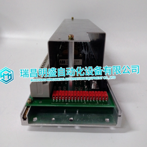
- Product ID: UNC4672A V1 HIEE205012R1 HI220957-31239
- Brand: ABB
- Place of origin: The Swiss
- Goods status: new/used
- Delivery date: stock
- The quality assurance period: 365 days
- Phone/WhatsApp/WeChat:+86 15270269218
- Email:stodcdcs@gmail.com
- Tags:UNC4672A V1HIEE205012R1HI220957-31239module
- Get the latest price:Click to consult
UNC4672A V1 HIEE205012R1 HI220957-31239 module
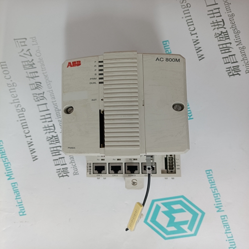
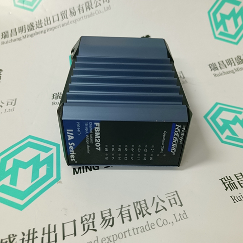
The green FLD PWR LED indicates the presence of both backplane power and field power for the analog field-side circuits. The OK LED indicates module status: On green indicates normal operation Flashing green indicates boot mode or update Flashing amber indicates self-diagnostic error Off indicates no 3.3V backplane power Carefully inspect all shipping containers for damage. If any equipment is damaged, notify the delivery service immediately. Save the damaged shipping container for inspection by the delivery service. After unpacking the equipment, record all serial numbers. Save the shipping containers and packing material in case it is necessary to transport or ship any part of the system.
Module features include:
Selectable resistance measurements in tenths of ohms, tenths of degrees Fahrenheit, or tenths of degrees Celsius Individual channel configuration Selectable resistance ranges: 0 – 500 ohms and 0 – 3000 ohms Selectable RTD input as resistance or temperature (Celsius or Fahrenheit) Reports high/low, underrange/overrange, open wire and input short alarms. Two data acquisition rates based on 50 Hz and 60 Hz line frequencies Configurable channel activation The module automatically performs A/D calibration at powerup. Automatic calibration is then repeated periodically to compensate for changes in the ambient temperature.
Cable Shield Connections
If possible, the cable should be grounded at the source device. If that is not possible, the cable shield must be grounded at the source device. If that is not possible, the cable shield must be grounded at the I/O module. This can be done using an Auxiliary I/O Terminal (IC200TBM001, 002, or 005). If the module is installed on a Terminal-style I/O Carrier (IC200CHS001, 002, or 005), shield connections can be made on an Auxiliary I/O Terminal that is attached to the I/O carrier. If the module is installed on a Compact Terminal-style I/O Carrier (IC200CHS022, 025), shield connections can be made on an Auxiliary I/O Terminal that is mounted near the I/O carrier. Be sure to ground the Auxiliary I/O Terminal Strip if you plan to use it for this purpose. If the module is installed on a Connector-style I/O Carrier (IC200CHS003), the cable shield can be connected directly to an Interposing Terminal (IC200CHS011, 012, 015). Be sure to ground the Interposing Terminal. It is recommended to use a shielded interposing cable as well between the Interposing Terminal and the Connector Base.