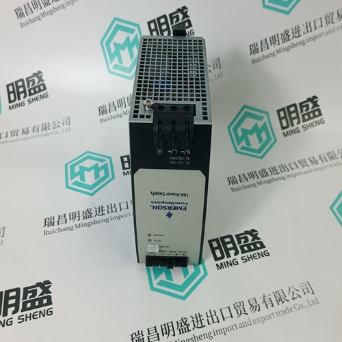
Home > Product > DCS control system > REF542plus 1VCR007346 G0012 Operation panel
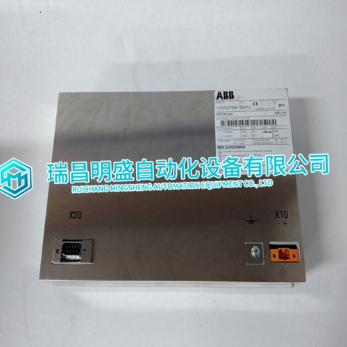
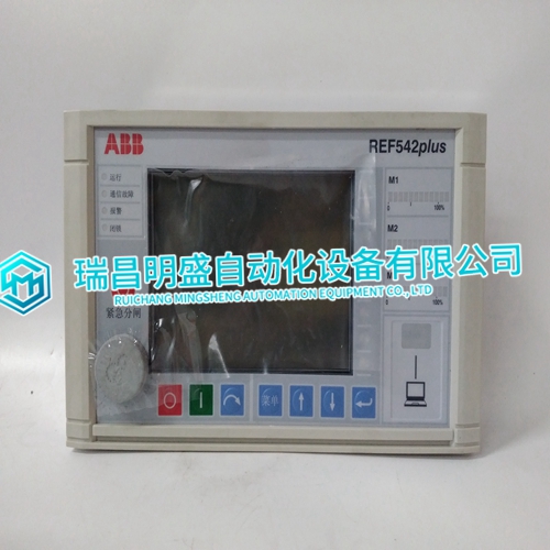
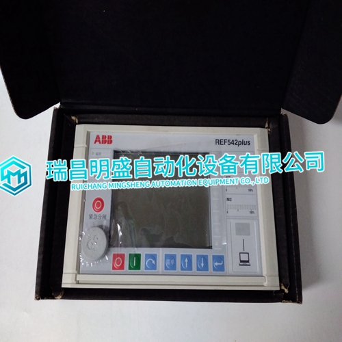
REF542plus 1VCR007346 G0012 Operation panel
- Product ID: REF542plus 1VCR007346 G0012
- Brand: ABB
- Place of origin: The Swiss
- Goods status: new/used
- Delivery date: stock
- The quality assurance period: 365 days
- Phone/WhatsApp/WeChat:+86 15270269218
- Email:stodcdcs@gmail.com
- Tags:REF542plus1VCR007346 G0012Operation panel
- Get the latest price:Click to consult
REF542plus 1VCR007346 G0012 Operation panel
Engine Protective Features
• High/Low Coolant Temperature • High/Low Oil Pressure
• Overspeed • Start Failure
• Six user configurable, discrete fault inputs Communication – PC Interface
• Easy upload and download of unit configuration parameters
• A PC can control or monitor any unit at a site via RS-422 serial port using Modbus® * or ServLink protocol
• For complete details see Communication Manual 26181
Hardware
The EGCP-2 is an integrated control package. All control hardware is contained in one compact enclosure. Figure 2-1 is a physical outline drawing with dimensions of the EGCP-2 for reference during the construction of mounting panels, etc. To mount the EGCP-2 panel use type M5 x 12mm thread forming screws (Woodward part number 1029-529). Eight mounting screws are shipped with each control. NOTE When mounting into an enclosure, make sure the enclosure is vented to atmosphere through a Type 4 vent tube or unsealed conduit.
Accessories
Components needed for installation and remote communication. These items do not ship with the 8406-120 and 8406-121 part numbers—they must be ordered separately.
• 8928-301—EGCP-2 connector kit. Contains all of the mating terminal blocks for the EGCP-2. See Appendix A for mating connector information.
• 5417-551—Communication Cable for RS422. This cable will connect your PC to the EGCP-2 RS422 port. This is a point-to-point connection. It can be used with EGCP-2 software tools. Communication Manual 26181 contains the software tool information.
