Home > Product > Gas turbine system > GE 44A751101-G01 Electrical module
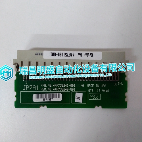
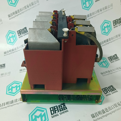
GE 44A751101-G01 Electrical module
- Product ID: 44A751101-G01
- Brand: GE
- Place of origin: The United States
- Goods status: new/used
- Delivery date: stock
- The quality assurance period: 365 days
- Phone/WhatsApp/WeChat:+86 15270269218
- Email:stodcdcs@gmail.com
- Tags:GE44A751101-G01Electrical module
- Get the latest price:Click to consult
GE 44A751101-G01 Electrical module
Potential Transformers (PTs) are utilized with the EGCP-2 control to allow high voltages to be stepped down to a safe level for the EGCP-2 input circuitry. The EGCP-2 control senses generator output voltage through three Generator PTs, and utility and plant-bus voltages via one shared utility/plant-bus PT.
Potential Transformer Input Ratings for 8406-120
Number of inputs: 4
Maximum Voltage Rating: 150–300 Vac
Burden: 0.45 VA
Input Frequency: 40–70 Hz
NOTE Because the same EGCP-2 input is used to sense both the utility and local bus voltages, the two PT signals must be identical in configuration (Wye or Delta), phase (A-B or A-N), and amplitude for correct input readings.
Generator PT Input Wiring
The EGCP-2 utilizes a 6-wire generator PT input configuration. This type of configuration allows the EGCP-2 to be easily wired to either Delta or Wye generators or transformers. The EGCP-2 control uses all three phases of the generator to sense both real and reactive generator power. Refer to the Figure 3-5 for Delta based wiring diagrams and Figure 3-6 for Wye based wiring diagrams. Once wired into a Delta or Wye circuit, the EGCP-2 must also be programmed to sense the correct (Delta or Wye) configuration.
Utility (Mains) and Plant Bus PT Input Wiring
The EGCP-2 utilizes one PT input to sense both utility tie-line voltage and plantbus voltage. This PT input must be the same configuration as the generator PT input. The potential transformer should be the same ratio as the generator PT input. Two Relay outputs are used by the EGCP-2 to select which voltage source to monitor, depending upon the state of the control. The EGCP-2’s control logic is set up to monitor the utility tie voltage during normal operation and local bus voltage when sensing for a dead bus condition or synchronizing the generator to the local bus. Refer to Figures 3-7 and 3-8, for required input wiring configurations. This type of configuration allows the EGCP-2 to perform a breakbefore-make relay action when switching between voltage sources to assure that the utility PT and Bus PT never are connected.