Home > Product > DCS control system > TRICONEX 9662-810 base module
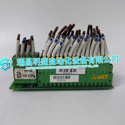
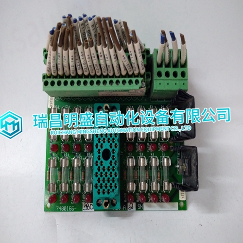
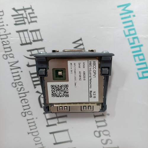
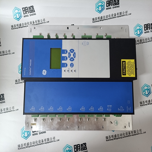
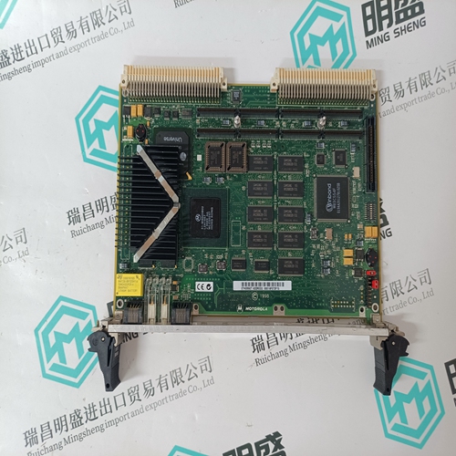
TRICONEX 9662-810 base module
- Product ID: 9662-810
- Brand: TRICONEX
- Place of origin: The United States
- Goods status: new/used
- Delivery date: stock
- The quality assurance period: 365 days
- Phone/WhatsApp/WeChat:+86 15270269218
- Email:stodcdcs@gmail.com
- Tags:TRICONEX9662-810base module
- Get the latest price:Click to consult
TRICONEX 9662-810 base module
Sequence of Mains PT Disconnect (DO8) and Local Bus PT Connect (DO7)
The EGCP-2 will command a Mains PT disconnect (DO8) when:
1. The EGCP-2 has an “AUTO” discrete input and either a. A loss of Mains (LOM) is detected or b. A “Run with load” discrete input.
2. The Generator Stable Delay time has been met.
3. The EGCP-2 is in the “Close Gen Breaker” mode. When the Mains PT Disconnect changes state, the EGCP-2 has to measure less than 40 Vac on the Mains/Bus PT input (terminals 40 and 41). If the EGCP-2 measures greater than 40 Vac after the Mains PT Disconnect command was given, the EGCP-2 senses this as a fault and will not synchronize.
For this reason, when only one PT signal is being connected, the external relay logic to remove the incoming Mains/Bus PT signal must still be applied. The following diagrams, Figures 3-7 and 3-8 show how to connect terminals 40 and 41 for different applications.
Required PT Wiring Relationships
The EGCP-2 control uses its programmed PT-Ratio setting to calculate and compare all PT input voltages. Thus, the EGCP-2 control requires the following generator, utility, and plant-bus PT relationships. Figures 3-9(a & b) and 3-10 (a & b) show these relationships.
Current Transformer (CT) Inputs
Current Transformers (CTs) are utilized with the EGCP-2 control to allow high currents to be stepped down to a safe level for the EGCP-2 input circuitry. The EGCP-2 senses generator current via external current transformers.
The “Amps per phase” display on the Generator Status screen:
1. does not display negative current
2. Must register at least 0.2 A on CT input before displaying any current Refer to Figure 3-11 for CT input wiring schematic. Current Transformer Input Ratings For optimum control, the Current Transformers (CTs) should be sized at 100 to 125% of the generators rated current.
