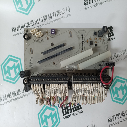
Home > Product > DCS control system > TRICONEX 9853-610 base module
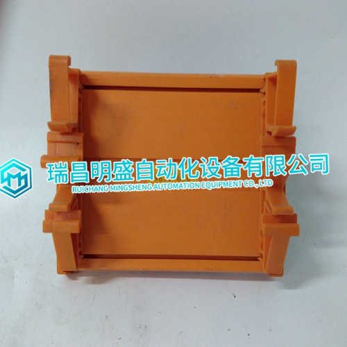
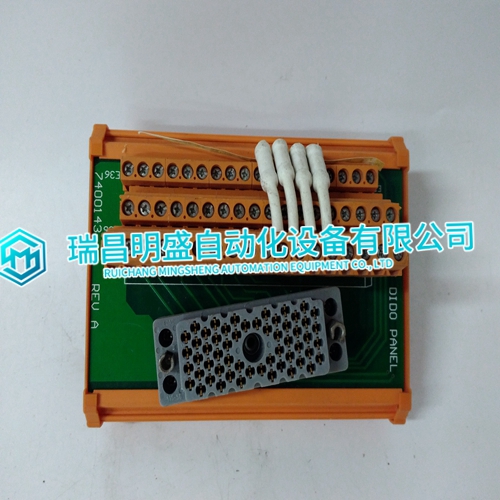
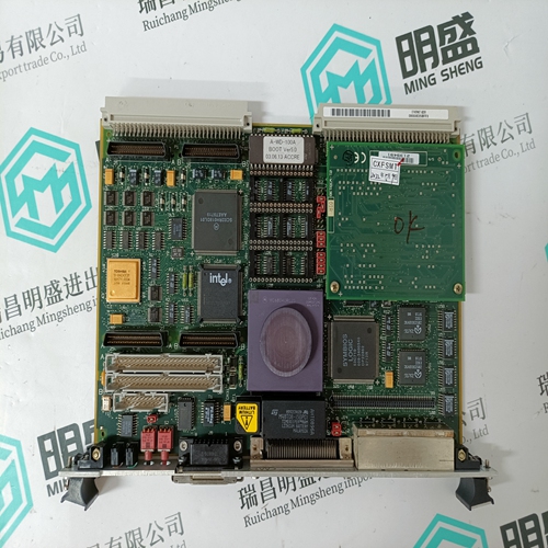
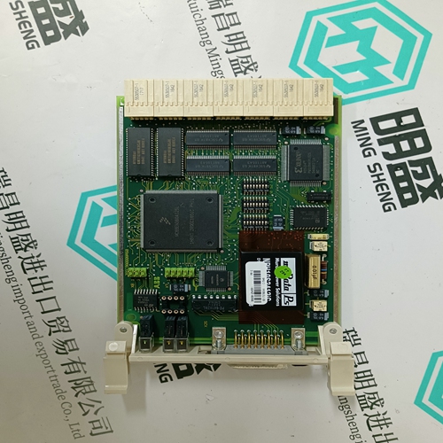
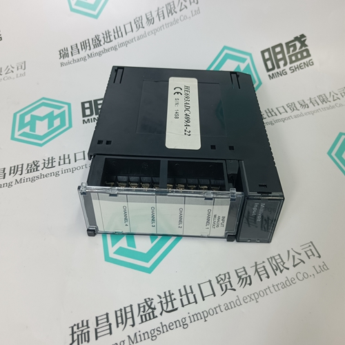
TRICONEX 9853-610 base module
- Product ID: 9853-610
- Brand: TRICONEX
- Place of origin: The United States
- Goods status: new/used
- Delivery date: stock
- The quality assurance period: 365 days
- Phone/WhatsApp/WeChat:+86 15270269218
- Email:stodcdcs@gmail.com
- Tags:TRICONEX9853-610base module
- Get the latest price:Click to consult
TRICONEX 9853-610 base module
To sense engine speed, the control accepts signals from one passive magnetic pickup unit (MPU) mounted off of a gear, which is connected or coupled to the engine’s main shaft. A passive MPU provides a frequency output signal corresponding to engine speed by sensing the movement of a gear’s teeth past the MPU’s pole piece. The closer the MPU’s pole piece is to a gear’s teeth and the faster the gear turns the higher a passive MPU’s output amplitude will be. The EGCP-2 must sense an MPU voltage of 3.5 to 25 Vrms for proper operation
With proper MPU, gear size, and MPU-to-gear clearance, speed measurement should be capable down to 100 Hz. Standard MPU clearance is recommended to be 0.010” to 0.040” from tooth face to pole piece. For information on selecting the correct MPU or gear size please refer to Woodward manual 82510. See Figure 3-13 for wiring schematic.
Process Import/Export Input
The EGCP-2 control can be configured to control any process that is determined or affected by generator load. The Process Import/Export input is used by the EGCP-2 control to sense the process level being controlled. This input can be DIP switch, switch 4, configured to accept either a 4–20 mA or 1–5 Vdc signal. Refer to Figure 3-4 for DIP switch location.
Process Input Ratings
Loop Voltage Source: External (4–20 mA), External (1–5 Vdc)
Input Impedance: 249 Ω (4–20 mA), 30 000 Ω (1–5 Vdc)
When connecting a kW transducer signal to multiple EGCP-2s, Woodward recommends converting the 4–12–20 mA signal to a 1–3–5 Vdc signal by connecting a 250 Ω resistor across the output of the kW transducer. The Vdc signal can then be paralleled to all EGCP-2 controls.
