Home > Product > Robot control system > COMPACTPCI DMV2400A-CPCI Pulse output module
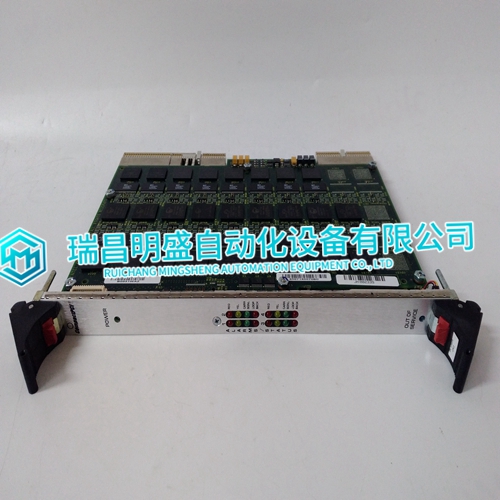
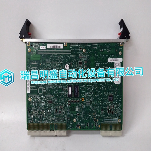
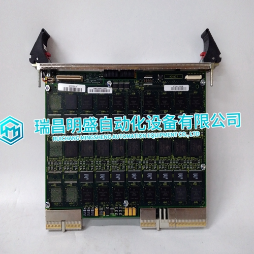
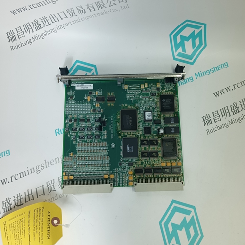
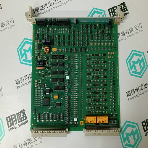
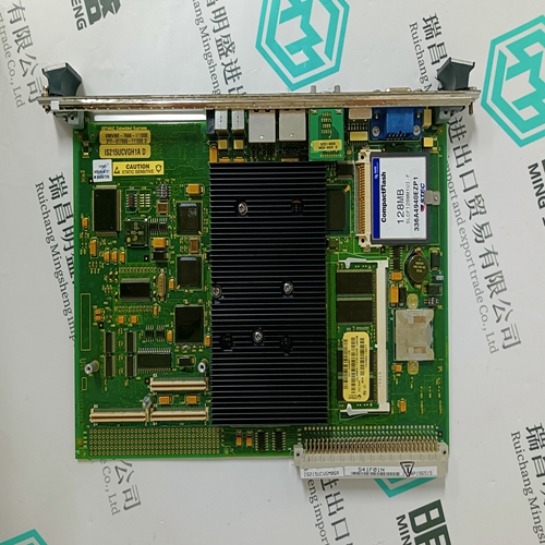
COMPACTPCI DMV2400A-CPCI Pulse output module
- Product ID: DMV2400A-CPCI
- Brand: COMPACTPCI
- Place of origin: The United States
- Goods status: new/used
- Delivery date: stock
- The quality assurance period: 365 days
- Phone/WhatsApp/WeChat:+86 15270269218
- Email:stodcdcs@gmail.com
- Tags:COMPACTPCIDMV2400A-CPCIPulse output module
- Get the latest price:Click to consult
COMPACTPCI DMV2400A-CPCI Pulse output module
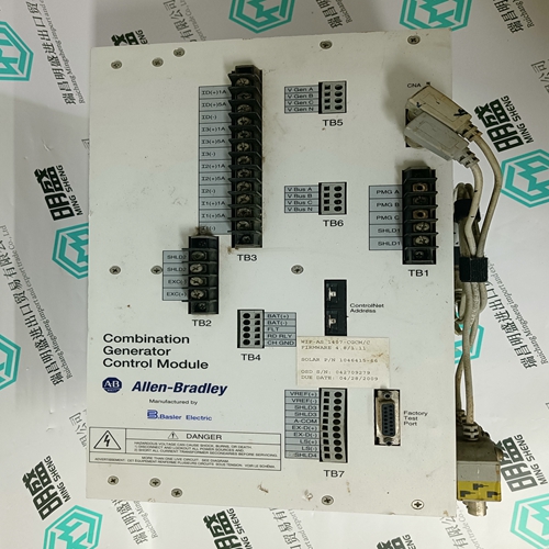
The EGCP-2 has one analog input dedicated to sense engine coolant temperature and one analog input dedicated to sense engine oil pressure. These inputs can be utilized for monitoring, alarm, and shutdown. Configurable alarm set points are provided for both a high and low alarms. Either one or both of these inputs can also be disabled if they are not to be used, by setting the related alarm set point to “Disabled.” The inputs are designed to accept one of three types of signals: 4-20 mA, 1-5 V, or a passive resistive sensor. DIP switches on the control circuit board need to be configured for the type of sensor being used (see Figures 3-14 and 3-15). Once the sensor type is selected and the DIP switches are set, the inputs should be calibrated for proper monitoring. Each input has an associated Gain and Offset setting in the Calibration menu. The controls are calibrated at the factory for a 4–20 mA sensor type that represents a 0–75 psi pressure signal and a 0–300 °F temperature signal. If a different range 4–20 mA, 1–5 V, or passive resistive sensor is used, the Gain and Offset values will need to be adjusted.
When selected for resistive sensor
three additional shunt resistors are provided to match the impedance range of the given sensor, to provide more range and accuracy. These inputs are designed to work with a variety of manufacturer’s sensors. Sensors can have a Direct or Indirect relationship. • Direct—Increase in Resistance, mA, or volts is an Increase in Pressure or Temperature. • Indirect—Increase in Resistance, mA, or volts is a Decrease in Pressure or Temperature. You must verify how the sensor functions so you can calibrate correctly. The Calibration menu explains adjusting the Gain and Offset for the different sensors.
Speed Bias and Voltage Bias Outputs
The EGCP-2’s Speed Bias output is a dedicated analog output, which is used to bias the prime mover’s speed control for unit synchronization and load control. The Speed Bias output is software configurable for outputs of ±3 Vdc, 0.5–4.5 Vdc, or 500 Hz PWM. ±3 Vdc—Compatible with Woodward analog and digital speed Controls via the Aux Inputs or the load sharing lines on the 2301/2301A LSSC. 0.5–4.5 Vdc—Compatible with the Detroit Diesel Corp. DDEC-III and IV Control and Caterpillar’s Gas Engine Control Module (GECM). 500 Hz PWM—Compatible with Caterpillar’s ADEM control (diesel engine). Refer to Appendix B of this manual for control specific speed bias connections.
