Home > Product > DCS control system > TRICONEX FTA-554 base module
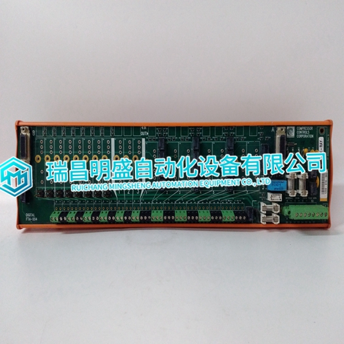
TRICONEX FTA-554 base module
- Product ID: FTA-554
- Brand: TRICONEX
- Place of origin: The United States
- Goods status: new/used
- Delivery date: stock
- The quality assurance period: 365 days
- Phone/WhatsApp/WeChat:+86 15270269218
- Email:stodcdcs@gmail.com
- Tags:TRICONEXFTA-554base module
- Get the latest price:Click to consult
TRICONEX FTA-554 base module
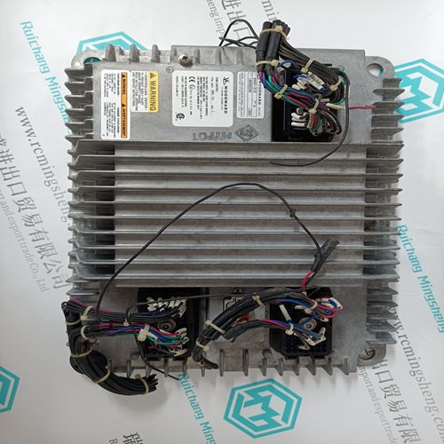
The “Engine Crank” relay output utilizes a set of Normally Open (NO) contacts on terminals 15 and 16. The “Engine Crank” relay output is utilized by the EGCP-2 to command the engine to crank or start. This relay will energize for a programmed length of time, based on the “Crank Time” setting, or until engine speed is sensed to be above the “Crank Cutout” speed setting. Discrete Output #6—Visual Alarm With the relay de-energized, this output has Normally Open (NO) terminals 18 and 19 and Normally Closed (NC) terminals 19 and 20 contacts to select from. The “Visual Alarm” relay output can be utilized as an option to remotely indicate when an alarm condition has been sensed by the EGCP-2 control. This relay energizes upon any sensed alarm condition and will remain energized until all alarm conditions have been acknowledged or committed via the unit’s Alarm Screen. Refer to chapter 2 for information on acknowledging and committing alarms.
Discrete Output #7—Local Bus PT Connect
The “Local Bus PT Connect” relay utilizes a set of Normally Open (NO) contacts on terminals 21 and 22. The “Local Bus PT connect” relay output is utilized by the EGCP-2 to connect the Local Bus PT to the EGCP-2’s “Utility and Local Bus PT Input” on terminals 40 and 41. Due to relay load limitations, it is required that this output be configured to drive an interposing relay with which to control the Local Bus PT connection. Refer to Figures 3-7 and 3-8 of this chapter for detailed wiring information. This type of relay configuration allows a break-before-make action, insuring that the Utility Tie PT and the Local Bus PT are never connected.
Discrete Output #8—Utility Tie (Mains) PT Disconnect
The “Utility Tie (Mains) PT Disconnect” relay utilizes a set of Normally Open (NO) contacts on terminals 23 and 24. The “Utility Tie (Mains) PT disconnect” relay output is utilized by the EGCP-2 to disconnect the Utility PT from the EGCP-2’s “Utility and Local Bus PT Input” on terminals 40 and 41. Due to relay load limitations, it is required that this output be configured to drive an interposing relay with which to control the Utility Tie PT connection. Refer to Figures 3-7 and 3-8 of this chapter for detailed wiring information. This type of relay configuration allows a break-before-make action, insuring that the Utility Tie PT and the Local Bus PT are never connected.