Home > Product > DCS control system > GDC806A0101 3BHE028761R0101 controller module
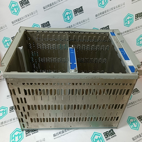
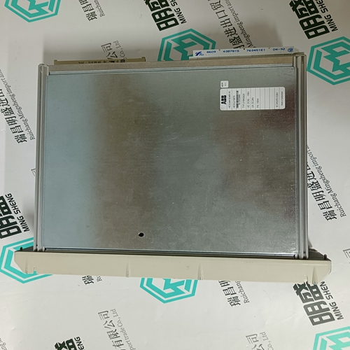
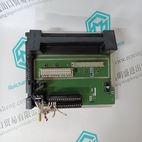
GDC806A0101 3BHE028761R0101 controller module
- Product ID: GDC806A0101 3BHE028761R0101
- Brand: ABB
- Place of origin: The Swiss
- Goods status: new/used
- Delivery date: stock
- The quality assurance period: 365 days
- Phone/WhatsApp/WeChat:+86 15270269218
- Email:stodcdcs@gmail.com
- Tags:GDC806A01013BHE028761R0101controller module
- Get the latest price:Click to consult
GDC806A0101 3BHE028761R0101 controller module
When the RS-422 to RS-232 converter is greater than 30 meters from unit 1, an isolating version will be required. Cable shields must also be AC coupled to earth or connected to RS-422 to RS-232 converter chassis. This chassis must be Isolated from earth and may be AC coupled to earth. When unit 2 and/or unit 3 are more than 30 meters from unit 1, the cable shield must be ac coupled to terminal 83. The capacitor must be 0.01 µF with a working voltage of 1000 Vdc or greater. The RS-422 Termination switches, switch 3, must be closed on the end units on the network for proper communications. See Figure 3-4 for switch locations. Failure to terminate the network properly will cause communication drop out errors.
Inter-control Communications
The EGCP-2 uses a proprietary communication structure to share information between multiple EGCP-2 controls. This structure allows accurate load sharing, status, and command messages to be exchanged between up to 8 controls. The network uses RS-485 protocol over a standard twisted shielded pair to link the EGCP-2 controls at terminals 76(+) and 77(–) with 78 the shield As shown in Figure 3-26, the EGCP-2 uses Switch 4 (4-1, 4-2, and 4-3) to terminate the 485 network. Switches 4-1, 4-2, and 4-3 will be closed (pushed down toward the PC board, see Figure 3-4) for proper 485 network terminations. Proper network termination will ensure robust inter-control communications.
NOTE
When EGCP-2 controls are installed with a distance of 1000 m or greater between them, additional measures should be taken to ensure solid communications. The wire gauge of the communications link should be upgraded to 0.5–0.8 mm² (18–20 AWG) where larger sizes are used for longer distances. The larger size wire will exhibit smaller voltage drop. If communications errors are observed, terminal 80 can be connected from control to control using 1.0 mm² (16 AWG) wiring. Making this connection will force all communications transceivers to the same reference.
