Home > Product > DCS control system > GDD360C 3BHE047217R0101 controller card
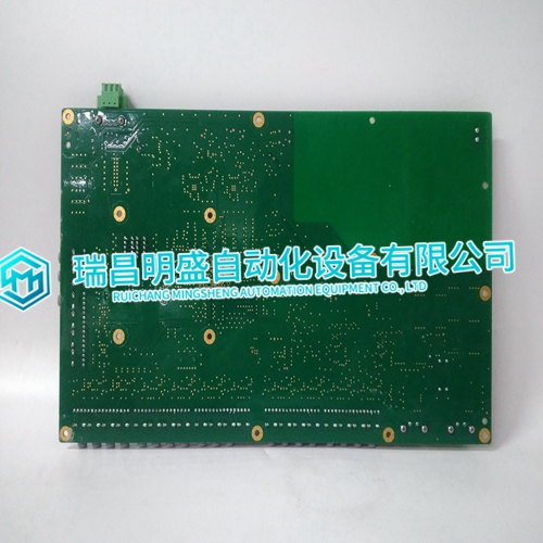
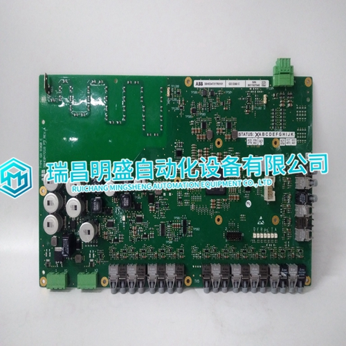
GDD360C 3BHE047217R0101 controller card
- Product ID: GDD360C 3BHE047217R0101
- Brand: ABB
- Place of origin: The Swiss
- Goods status: new/used
- Delivery date: stock
- The quality assurance period: 365 days
- Phone/WhatsApp/WeChat:+86 15270269218
- Email:stodcdcs@gmail.com
- Tags:GDD360C3BHE047217R0101controller card
- Get the latest price:Click to consult
GDD360C 3BHE047217R0101 controller card
The information on the RS-485 network is for communications between controls only and must not be interfaced in any way with external devices. There is an RS-422 port on the EGCP-2, which is used to monitor and control the units remotely.
Example: 2 EGCP-2s—Both EGCP-2s must have the 485 network terminated. 3 or more EGCP-2s—
1. The end controls must have the 485 network terminated (see Figure 3-27).
2. Terminals 79 and 80 should be connected from control to control a. This eliminates signal loss if one of the terminated controls is powered down.
Alarms and Shutdowns
The EGCP-2 has many alarm/shutdown set points, which can be configured for five different alarm/shutdown conditions. The five conditions are as follows: Disabled When an alarm set point is set for Disabled, the alarm condition will have no external indicators to signal the event has occurred. No control actions occur as a result of a disabled condition.Warning When an alarm set point is set for Warning, the alarm condition will cause the red LED on the face of the EGCP-2 to flash continuously until the alarm condition is acknowledged. No control actions occur as a result of a warning condition.
Visual Alarm
When an alarm set point is set for Visual Alarm, the alarm condition will cause the visual alarm output relay to energize, and the red LED on the face of the EGCP-2 to Flash. Both indicators will remain active until the alarm condition is acknowledged. No control actions occur as a result of a visual alarm condition. Audible Alarm When an alarm set point is set for Audible Alarm, the alarm condition will cause the audible and visual alarm output relays to energize and the red LED on the face of the EGCP-2 to flash. All alarm indicators will remain active until the alarm condition is acknowledged. No control actions occur as a result of an audible alarm condition.

