Home > Product > Gas turbine system > HYDRAN M2 transformer
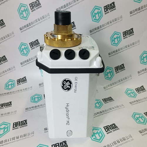
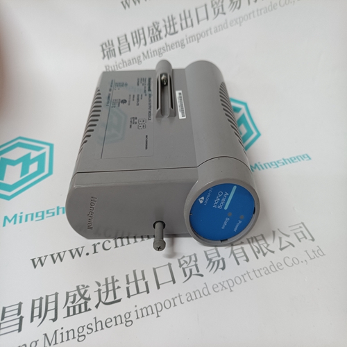
HYDRAN M2 transformer
- Product ID: HYDRAN M2
- Brand: GE
- Place of origin: the United States
- Goods status: new/used
- Delivery date: stock
- The quality assurance period: 365 days
- Phone/WhatsApp/WeChat:+86 15270269218
- Email:stodcdcs@gmail.com
- Tags:HYDRAN M2transformer
- Get the latest price:Click to consult
The main products
Spare parts spare parts, the DCS control system of PLC system and the robot system spare parts,
Brand advantage: Allen Bradley, BentlyNevada, ABB, Emerson Ovation, Honeywell DCS, Rockwell ICS Triplex, FOXBORO, Schneider PLC, GE Fanuc, Motorola, HIMA, TRICONEX, Prosoft etc. Various kinds of imported industrial parts
HYDRAN M2 transformer
The comparison time ‘t comp’ The comparison time is the time allowed for the directional comparison to be made and is therefore dependent on the type of transfer tripping scheme. The comparison time has a fixed setting of 1 s. 3.5.28.9. Setting the waiting time ‘t wait’ The waiting time is also started at the end of the basic time, but is only effective in a blocking scheme.In a blocking scheme, tripping is delayed by the setting of ‘t wait’ to allow time for the protection in the opposite station to decide on the direction of the fault and to transmit a corresponding blocking signal if necessary. ‘t wait’ should be set at least as long as the measuring time (about 30 ms) plus the longest possible signal transmission time. 3.5.28.10. Setting the transient blocking time ‘t TransBlk’ The protection function includes a "transient blocking logic" to prevent any mal-operation during the course of tripping a fault or auto-reclosure on double-circuit lines, when there is a likelihood of the flow of energy reversing direction. The time setting can be selected in a wide range to suit the prevailing conditions. For example, after a fault has been detected in the backwards direction, a second directional decision in the forwards direction is inhibited for the setting of ‘t TransBlk’ . The time chosen is determined largely by the time required for the measurement to reset and the transfer tripping scheme in use. The recommended setting is 60 ms plus the reset time of the communication channel.
Analogue inputs of the function
Where the zero-sequence components of the voltages and the currents are derived internally, the analogue inputs must be connected precisely as shown in the wiring diagram. The neutral of the c.t’s in this case is formed on the line side and the parameter ‘CT neutral’ must be set to ‘line side’ . 3.5.28.12. Binary inputs of the function Ext. block Exciting the ‘Ext. block’ I/P disables the entire protection function. Receive The signal transmitted by the protection in the opposite station is connected to this I/P.CB position The ‘CB position’ I/P is intended for the position indicator signal from the circuit-breaker and has a fixed pick-up delay of 50 ms. The protection function is only enabled when this signal is received to confirm that the CB is closed. The corresponding auxiliary contacts for the three phases must be connected in series to ensure that the protection does not operate during single-phase reclosure. The echo logic is enabled 100 ms after the circuit-breaker is opened. VT Supervision The ‘FuseFail’ I/P (v.t. supervision) is needed to block the echo logic. It can be excited either by the ‘VTSup’ signal from the internal distance protection function or an auxiliary contact on the m.c.b. via a binary I/P. If this I/P is not needed, it must be set to “F”. Ext Start R / S / T, Ext Trip 3P, Ext Trip These I/P’s are for coordinating operation with the distance protection function. To them are connected the distance function signals ‘Start R’, ‘Start S’, ‘Start T’, ‘Trip CB 3P’ and ‘Trip CB’. They must be set to “F” if an independent directional E/F scheme is in use.
