Home > Product > DCS control system > GVC736CE101 3BHE039203R0101 5SXE12-0184 card
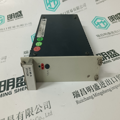
GVC736CE101 3BHE039203R0101 5SXE12-0184 card
- Product ID: GVC736CE101 3BHE039203R0101 5SXE12-0184
- Brand: ABB
- Place of origin: The Swiss
- Goods status: new/used
- Delivery date: stock
- The quality assurance period: 365 days
- Phone/WhatsApp/WeChat:+86 15270269218
- Email:stodcdcs@gmail.com
- Tags:GVC736CE1013BHE039203R01015SXE12-0184card
- Get the latest price:Click to consult
GVC736CE101 3BHE039203R0101 5SXE12-0184 card
This is what the System Status screen would look like with the mains out of spec, the engine running, carrying 100 kW load isochronously, and the generator voltage and frequency is within specified limits. This would be a typical screen if the unit was set for loss of mains detection, and the mains had failed.This is what the System status screen looks like for a generator set that is base loaded to the mains at 500 kW, 0.80 lagging PF, with one unacknowledged alarm.
Generator voltage label, VLL—Voltage Line-to-Line or VLN—Voltage Line-toNeutral will be determined from the Voltage Input configuration setting. Generator voltage readings and labels will automatically switch from “V” (volts) to “KV” (kilovolts), when the voltage exceeds 9999 V for that input.
The slip frequency in Hz. of the generator
in relation to the bus or mains it is paralleling to. Phase: The phase angle difference in degrees between the generator and the bus or mains it is paralleling to. Volts: The voltage differential in percent between the generator and the bus or mains it is paralleling to. Mains/Bus: The active PT input being monitored by the EGCP-2. Dead Bus: Indicates if the PT input (mains or bus) being measured is dead.The total, three phase kW the generator is producing. Load Reference: The load reference, in kW for the generator. System Load: The calculated system load for all units operating in isochronous load sharing mode. This reading is NOT active in the Baseload mode.
Security Code Required For Access
The EGCP-2 has built-in security to protect against configuration changes and alarm purges by unauthorized personnel. There are five levels of access to the configuration menus. They are listed below. Each successive level has access to all of the levels above. A four-digit security code is required for access to the configuration menus. If an incorrect code is entered, or a proper code is not entered within 300 seconds, the displays will default to the last Status screen selected. Levels Of Access Monitor (no security code) Access to all Status Screens, view Alarm / Event Log Display, and ability to commit (clear) an Audible Alarm. Operator Access to view and clear Alarm / Event Log and change the Network Priority.