Home > Product > Gas turbine system > IS210AEBIH1BED Gas turbine module
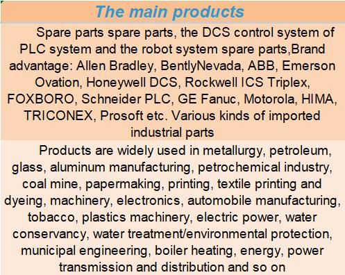
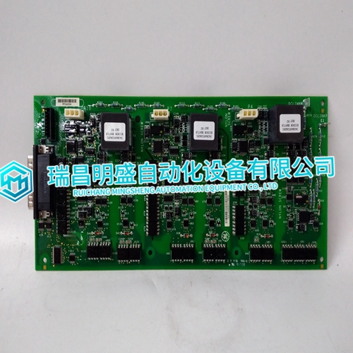
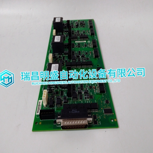
IS210AEBIH1BED Gas turbine module
- Product ID: IS210AEBIH1BED
- Brand: GE
- Place of origin: The United States
- Goods status: new/used
- Delivery date: stock
- The quality assurance period: 365 days
- Phone/WhatsApp/WeChat:+86 15270269218
- Email:xiamen2018@foxmail.com
- Tags:IS210AEBIH1BEDGas turbine module
- Get the latest price:Click to consult
IS210AEBIH1BED Gas turbine module
The control compares the Process Input signal to the Process Reference set point in the Process menu of the EGCP-2. This set point uses milliamps for units, so that it is easily related to the 4–20 mA or 1–5 Vdc input signal. The EGCP-2 then adjusts the generator load to maintain the desired value. The EGCP-2 will only operate in a process control mode if it is configured to be a Mains Parallel unit, and receives an Auto, Run With Load, and Process discrete inputs. Also, the EGCP-2 can operate in a process soft transfer mode if the Load Control Mode set point in the Real Load Control menu is set for Soft Transfer, and the Test discrete input is closed with the Auto, Run with Load and Process discrete inputs. In a soft transfer mode, the EGCP-2 will load the generator(s) (depending on the application) to the process reference level. Upon reaching the reference value on the 4–20 mA or 1–5 Vdc input signal, the EGCP-2 will open the mains breaker. This Soft Transfer mode is used to transfer the supply of power for the load from the mains to the generator(s).
In process control mode
the Raise Load and Lower Load Discrete Inputs operate on the process control reference. The ramp rates for these Raise and Lower Load inputs are set in the Process menu, at the Process Raise and Process Lower Rate. These two set points are scaled in % per second. When the process function is initially selected, the reference is set equal to the internal process reference. If the process input and process reference are not equal, the control ramps the load reference in the appropriate direction to reduce the difference. When the process error reaches zero, the process control is enabled.
When the process control is enabled
the error signal between the process reference and process signal is routed to a PID (Proportional, Integral, Derivative) controller operating in cascade with the load control. The output of the controller is a load reference, which is limited by the kW Load High and Low Limit set points in the Real Load Control menu. This prevents the generator from being overloaded or reversed powered to achieve its reference point. In a multiple unit, mains parallel configuration, the master unit (lowest numerical priority) operates as the Process Master. The master unit must receive the 4–20 mA, or 1–5 Vdc process input signal. The master unit will control all slave units, which are in Auto mode to maintain the process reference of the master. The slave units operate in a load sharing mode in which the total system load is equally divided between the units in proportion to their rated load capacity. The master will also automatically sequence slave units on and off as required to maintain the process reference.
