Home > Product > DCS control system > EPRO PR9268/307-100 9200-06121n front-end
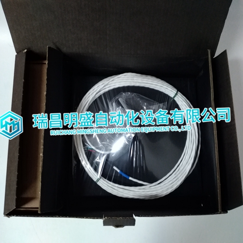
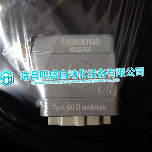
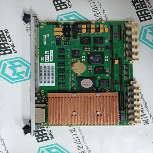
EPRO PR9268/307-100 9200-06121n front-end
- Product ID: PR9268/307-100 9200-06121n
- Brand: EPRO
- Place of origin: The United States
- Goods status: new/used
- Delivery date: stock
- The quality assurance period: 365 days
- Phone/WhatsApp/WeChat:+86 15270269218
- Email:stodcdcs@gmail.com
- Tags:EPROPR9268/307-100 9200-06121nfront-end
- Get the latest price:Click to consult
EPRO PR9268/307-100 9200-06121n front-end
If a synchronous generator is paralleled to a larger system such as a Mains, a difference in voltages before paralleling will not change the voltage of the bus. If the generator voltage is lower than the bus voltage, reactive power will be drawn from the bus and used to excite the generator to the higher bus voltage. In the case where the generator voltage is low enough, the reactive power flow could motorize the generator with potential damage to the generator windings. The microprocessor then computes the RMS values of the voltages. The processor issues appropriate adjustment of the voltage bias signal if used, to the voltage regulator to bring the generator voltage within the specified window above the bus voltage. To guarantee that reactive power will be generated, window range is from equal to bus voltage to the specified percentage above bus voltage.
The automatic voltage matching function
may be enabled or disabled with a set point. When enabled, voltage matching will occur in both the Check and Run modes and is verified only by the sync-check function in Permissive mode. When enabled at an EGCP-2 control that is monitoring and controlling the mains breaker, the voltage matching will occur across both the generator and mains breaker prior to the synchronizer issuing a breaker close command when paralleling the generator(s) to the mains.
Phase Matching Synchronizing
The phase matching synchronizing mode corrects the frequency and phase of the generator to lock it to the bus frequency and phase. The microprocessor uses signal processing techniques to derive the difference in phase of the generator A and bus A phase voltage signals. When there is a difference, the synchronizer sends a correction signal to the speed control. The correction signal from the speed bias output increases or decreases engine speed depending on whether the slip is faster or slower than the bus. A PI (proportional, integral) controller provides the correction signal. Gain and Stability adjustments to the PI controller are provided to allow stable operation of the automatic synchronizer function over a wide range of system dynamics.