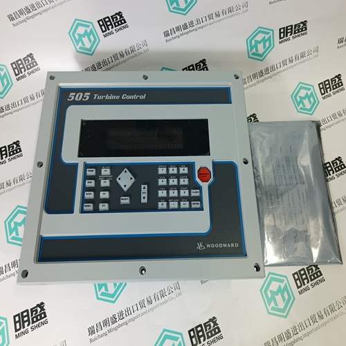
Home > Product > DCS control system > HONEYWELL CC-PAIN01 51410069-175 module
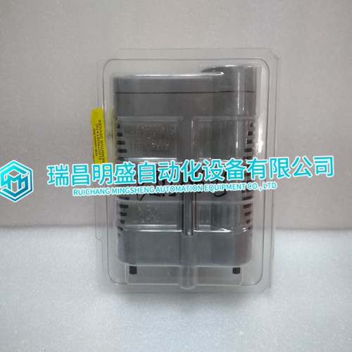
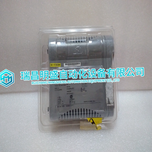
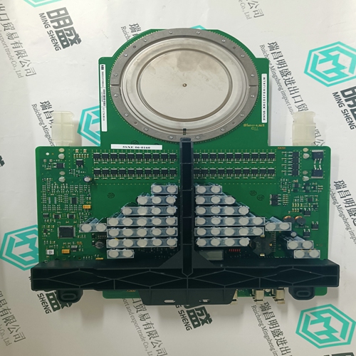
HONEYWELL CC-PAIN01 51410069-175 module
- Product ID: CC-PAIN01 51410069-175
- Brand: HONEYWELL
- Place of origin: The United States
- Goods status: new/used
- Delivery date: stock
- The quality assurance period: 365 days
- Phone/WhatsApp/WeChat:+86 15270269218
- Email:stodcdcs@gmail.com
- Tags:HONEYWELLCC-PAIN0151410069-175module
- Get the latest price:Click to consult
HONEYWELL CC-PAIN01 51410069-175 module
Mains Parallel Units Follow these steps if you are configuring a Mains Parallel Master Unit, or a Mains Parallel Slave unit, which will operate as a redundant master. Redundant master units must have the Mains CB Aux hardwired into them. All other wiring to the Master and Redundant Master Units must be identical for proper operation of the redundant units in the event of a loss of master.
1. Set load/unload ramp times to at least 60 seconds.
2. Set base load level to 30% of rated load.
3. Start unit with an Auto and Run with Load Input. a. Unit will start and attempt to synchronize.
4. Adjust synchronizer dynamics for best control of phase matching (monitor synchroscope status menu to see phase error.).
5. Use voltmeter to check voltage across generator breaker to assure proper phase rotation and mains PT input polarity.
6. Shut down the unit by removing the Auto and Run with Load Inputs.
7. Set synchronizer to run mode. 8. Start unit with an Auto and Run with Load Input.
No Parallel and Slave Setup
Use the following instructions for setup of No Parallel Applications, and Slave unit applications. 1. Set unit for LOM on mains under frequency.
2. Set Check Mains Breaker = disabled.
3. Set Dead Bus Closing = enabled.
4. Remove mains PT and mains CB Aux input by opening mains breaker if necessary.
5. Start unit with auto switch input.
6. Unit will start and close generator breaker to bus. a. Verify dead bus closing. b. Apply load to unit using load bank or plant load as applies. c. Calibrate CT readings if needed.
7. If in a multi unit system, repeat previous steps for all units. Set all units to be tested synchronizers to check mode prior to start.
8. The unit currently on the bus carrying the load will act as a synchronizing reference for the other units.
Verify voltage matching
phase relationships of additional units by monitoring the synchroscope status menu. a. Verify voltage levels across generator breakers. 10. Tune individual synchronizer dynamics. a. Calibrate synchronizer if needed. 11. Once satisfied with each synchronizers operation, shut down these units by removing the auto input. 12. Change synch mode settings to run on all units. a. This will enable generator breaker closure to live bus. 13. Start one unit in auto and allow it to close to the dead bus. a. Verify isochronous operation. b. Verify correct voltage level on bus.
