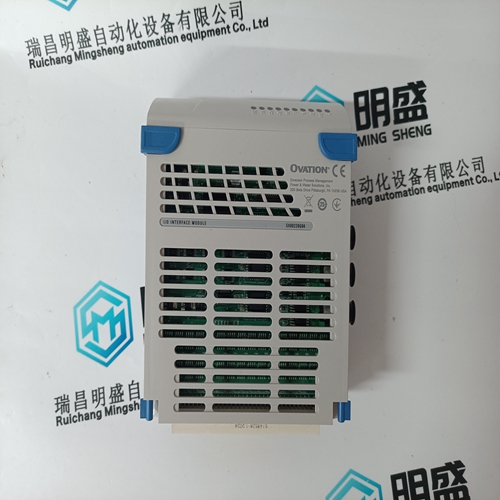
Home > Product > DCS control system > PM803F 3BDH000530R1 Control processor module
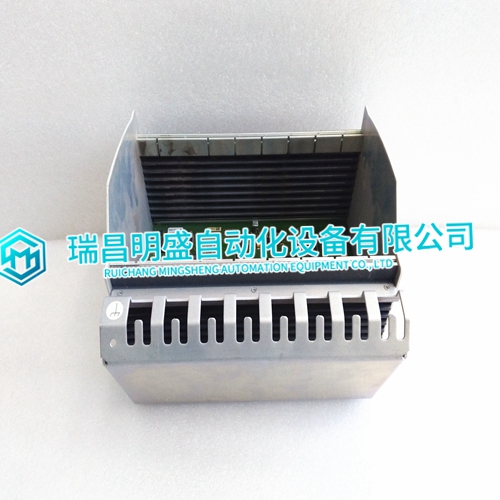
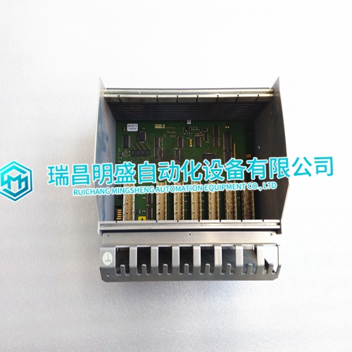
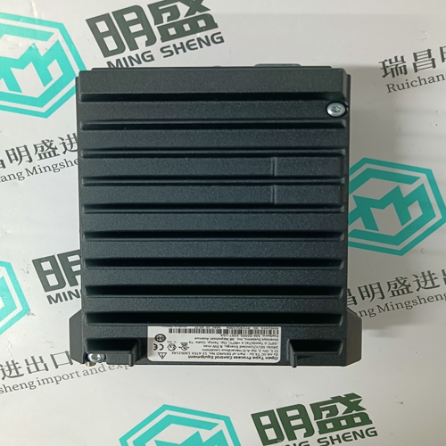
PM803F 3BDH000530R1 Control processor module
- Product ID: PM803F 3BDH000530R1
- Brand: ABB
- Place of origin: The Swiss
- Goods status: new/used
- Delivery date: stock
- The quality assurance period: 365 days
- Phone/WhatsApp/WeChat:+86 15270269218
- Email:stodcdcs@gmail.com
- Tags:PM803F3BDH000530R1Control processor module
- Get the latest price:Click to consult
PM803F 3BDH000530R1 Control processor module
Electronic modules can be removed from or inserted into the sockets without switching off the power supply. The behavior of connected field devices must be taken into consideration.
► Make sure that terminal socket and electronic I/O module match, see Table 4 on page 6.
► Make sure that the red locking mechanism is in the open, i.e., left, position.
► Gently push the electronic module onto the terminal socket until snug.
The red locking mechanism will not close if the electronic module is not properly mounted.
Dismounting Electronic Modules
Note Electronic modules can be removed from or inserted into the sockets without switching off the power supply. The behavior of connected field devices must be taken into consideration. ► Open the red locking mechanism by sliding it to the left and then gently pull the electronic module out of the terminal socket.
XS812 and XS812RO Manual Disconnect Modules are mounted on the terminal socket appropriate for the electronic module, see Table 4 on page 6. The electronic module is mounted onto the manual disconnect module.Risk of electric shock or equipment damage! The XS812RO Manual Disconnect Module is designed for 24 V applications only!
► Never use the XS812RO Manual Disconnect Module with line voltage.
Mounting Manual Disconnect Modules
► Make sure that manual disconnect module, electronic module, and terminal socket match, see Table 4 on page 6.
► Make sure that the red locking mechanism is in the open, i.e., left, position.
► Gently push the manual disconnect module onto the terminal socket until snug.
► Lock the red locking mechanism by sliding it to the right.
► Use a screwdriver to open/close the appropriate disconnector switches of the manual disconnect modules.
