Home > Product > DCS control system > 1C31116G04 Analog output card

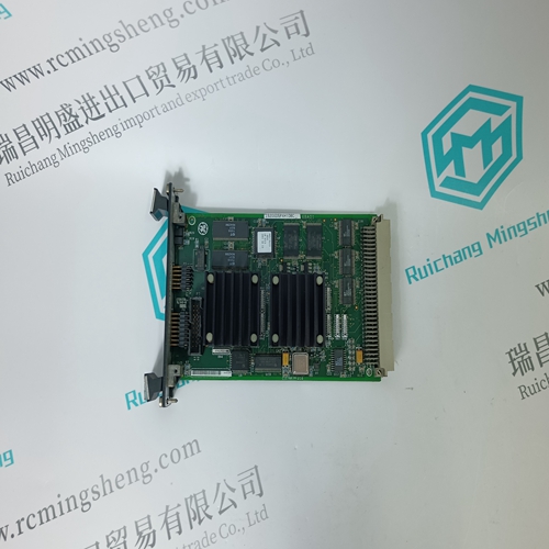
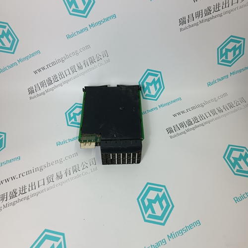
1C31116G04 Analog output card
- Product ID: 1C31116G04
- Brand: EMERSON
- Place of origin: The United States
- Goods status: new/used
- Delivery date: stock
- The quality assurance period: 365 days
- Phone/WhatsApp/WeChat:+86 15270269218
- Email:stodcdcs@gmail.com
- Tags:1C31116G04Analog output card
- Get the latest price:Click to consult
1C31116G04 Analog output card
During CARE engineering, each Panel Bus I/O module is assigned its own unique address. For the sake of clarity for maintenance personnel, it is recommended that you address the Panel Bus I/O modules in ascending order 0 through F.
► Use the rotary HEX switch to set the address to the one already defined during CARE engineering.
Notes • If the HEX switch is changed, the Panel Bus I/O module will revert to its default configuration.
• With LONWORKS Bus I/O modules, the HEX switch is without functi
Connecting Field Devices with Power Supply
Depending on the distance from the controller, field devices can be supplied by the controller or need a separate transformer, see Table 20 on page 13. For fusing see section "Fusing Specifications" on page 10. Example 1: Power Supply via Controller
• 24 V actuator connected to an analog output module
• Less than 100 m away from the controller
• 24 V actuator connected to an analog output module
• 100 … 400 m away from the controller
Cable Shielding
• If the general guidelines for cable routing are observed, it is not necessary to shield field device signal and power supply cables.
• If, for whatever reason, the routing guidelines cannot be observed, the field device signal and power supply cables must be shielded. – Shielding of cables leading to field devices must be grounded only at the cabinet end. – The shield must not be terminated at the XCL8010 Controller Module.
All low-voltage signal and output cables should be regarded as communication circuits in accordance with VDE 0100 and VDE 0800 (or NEC or other equivalent).