Home > Product > DCS control system > DSQC609 3HAC14178-1 PBSE5117 Teaching module
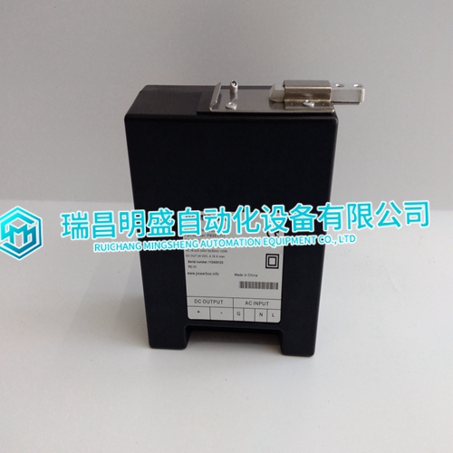
DSQC609 3HAC14178-1 PBSE5117 Teaching module
- Product ID: DSQC609 3HAC14178-1 PBSE5117
- Brand: ABB
- Place of origin: The Swiss
- Goods status: new/used
- Delivery date: stock
- The quality assurance period: 365 days
- Phone/WhatsApp/WeChat:+86 15270269218
- Email:stodcdcs@gmail.com
- Tags:DSQC6093HAC14178-1PBSE5117Teaching module
- Get the latest price:Click to consult
DSQC609 3HAC14178-1 PBSE5117 Teaching module
Analog Outputs Configured as Binary Outputs Using CARE, the analog outputs can be configured individually as binary outputs. The voltage output is then 0 V or 10 V, depending upon the signal from the controller.Status LED Behavior Using CARE, each of the twelve status LEDs can be configured individually for use as either alarm LEDs (red/green) or as status LEDs (yellow/OFF [default]). Given a logical state of "ON," the status LED will be lit (yellow or red).
Risk of malfunction!
Cross connectors may only be used if the same voltage is used on all relays they connect. ► Do not use a cross connector if different voltages are used on the relays. E.g., use a short cross connector for relay block 1 with line voltage and no cross connector for relay block 2 with 12 V low voltage for relay 4 and 24 V low voltage for relays 5 and 6.
Synchronization Behavior of Analog Output Module
Configured as Floating Output In order to regularly update the real actuator position with the calculated position and thus ensure that the actuator definitely reaches its end position, a synchronization process is performed by the analog output module. During the synchronization process, the analog output module will continue running for the configured runtime once it reaches the calculated end position.
This updating (synchronization) is performed: • If the calculated position of the actuator < lower synchronization threshold (2%) = synchronization towards 0% • If the calculated position of the actuator > upper synchronization threshold (98%) = synchronization towards 100% • Following any power-up or any reset
Manual Override in the AUTO Position
When a manual override of the …R824 Relay Output Module is set to the “AUTO” position, and the corresponding relay output has been configured, the following applies: • If the LONWORKS network is functioning properly, the logical status of the relay output will be “AUTO.” • If the LONWORKS network is not functioning properly, the feedback signal will be switched to the safety position value. • The feedback signal on the LONWORKS network: nvoDoActPosnFb[ ] will have a value of either 0% or 100%, and a state of -1. • The status LED (yellow) will indicate the actual logical state of the relay output as commanded (by nviDoSwitch[ ])
• In the case of voltages above 30 VAC/DC and if inductive components are to be connected to relays switching more often than once every 2 minutes, these components must be prevented from causing harmful interference to radio or television reception (conformance with EN 55014). • Max. voltage for UL 864-compliant applications is 24 V.