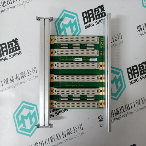
Home > Product > DCS control system > SPFEC12 Analog input card
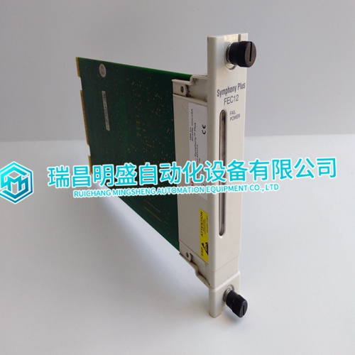
SPFEC12 Analog input card
- Product ID: SPFEC12
- Brand: ABB
- Place of origin: The Swiss
- Goods status: new/used
- Delivery date: stock
- The quality assurance period: 365 days
- Phone/WhatsApp/WeChat:+86 15270269218
- Email:stodcdcs@gmail.com
- Tags:SPFEC12Analog input card
- Get the latest price:Click to consult
SPFEC12 Analog input card
Configured Floating Relay Output If a floating relay output has been configured, the following applies: The corresponding manual override can be used to adjust the respective floating actuator so that it drives to any desired position between fully closed (0%) and fully open (100%). The "open" relay or "closed" relay – as the case may be – is then switched ON for the time the actuator requires to drive to the desired position, whereupon it will stop. This required time depends upon the configured motor runtime (time to open / time to close,) while the direction of movement is dependent upon the configured direct/reverse setting.
Unconfigured Floating Relay Output
If a floating relay output has not been configured (see Fig. 83), the following applies: Although the motor runtime is unknown to the XFR825, the corresponding manual override can be used during the commissioning phase to adjust the respective floating actuator so that it drives to any desired position between fully closed (0%) and fully open (100%). The "open" relay (relay "n," i.e. “1,” “3,” or “5”) and the "closed" relay (relay "n+1," i.e. “2,” “4,” or “6”) are then switched ON and/or OFF, respectively, when the corresponding manual override is set to "0…100%." Specifically, the actuator will drive towards its closed position as long as the manual override is set to "0…50%," and it will drive towards its open position as long as it is set to "50…100%." Setting the manual override to "AUTO" stops the actuator.
XS830 Auxiliary Terminal Package
Features • Type: XS830 Auxiliary Terminal Package • For mounting onto the top and/or bottom of alreadyinstalled XF830A mixed I/O modules and the top of already-installed XFU830A mixed I/O modules in order to equip them with additional terminals. • Each unit consists of two groups of terminal blocks (the "A" block and the "B" block), each with nine internally-connected push-in terminals with a maximum load of 12 A.