Home > Product > PLC programmable module > PROSOFT MVI56-PDPS Communication module
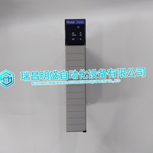
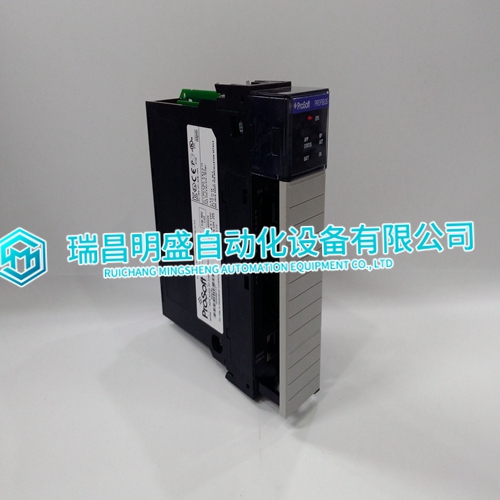
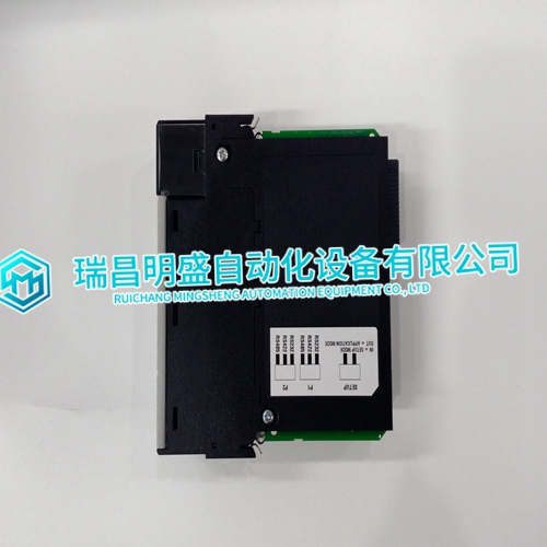
PROSOFT MVI56-PDPS Communication module
- Product ID: MVI56-PDPS
- Brand: PROSOFT
- Place of origin: The United States
- Goods status: new/used
- Delivery date: stock
- The quality assurance period: 365 days
- Phone/WhatsApp/WeChat:+86 15270269218
- Email:stodcdcs@gmail.com
- Tags:PROSOFTMVI56-PDPSCommunication module
- Get the latest price:Click to consult
PROSOFT MVI56-PDPS Communication module
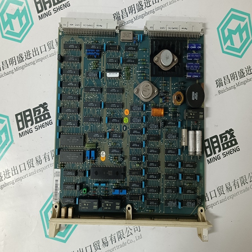
The ASI module communicates with the controller through a shared memory interface connected to the I/O expander bus. The ASI module constantly updates the shared memory device (dual port RAM) with the current values of the inputs. The controller can read these values at any time, even if the ASI module is simultaneously writing to the dual port RAM. The ASI module uses a custom gate array for the I/O expander bus interface. An integrated circuit holds all the control logic and communication protocol. This integrated circuit provides these functions: • Address comparison and detection. • Message decoding and translation. • Data line filtering of bus signals. • Onboard bus drivers. • Expander bus watchdog. A dual port RAM stores data that can be accessed at the same time by the controller and the I/O module's microcontroller.
Data Values
For all inputs, channel values are adjusted based on the factory calibration. Thermocouple inputs receive cold junction reference compensation. Lead wire resistance adjustments are performed when necessary (for cold junction reference only). The ASI module provides values to the controller over the I/O expander bus. These values are in engineering units. The ASI module sends a status indication to the controller for each input channel. This status indicates any hardware errors and channel configuration errors detected by the ASI module.
Termination Units
The IMASI13 module uses one NTAI06 termination unit to connect to field signals. An NKAS01 or NKAS11 cable connects the termination unit to the ASI module through its P3 connector. The termination unit contains RTDs used for cold junction compensation of thermocouple inputs. They also contain the circuitry needed to convert 4 to 20 milliampere field signals into the 1 to 5 VDC needed to input to the analog input module. The system power supply is protected from short circuits by fuses on the NTAI06 termination unit.
