Home > Product > DCS control system > 12P3162X162 SLS 1508 Analog input module
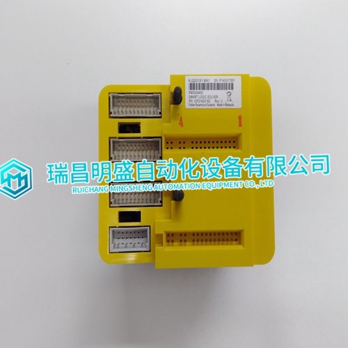
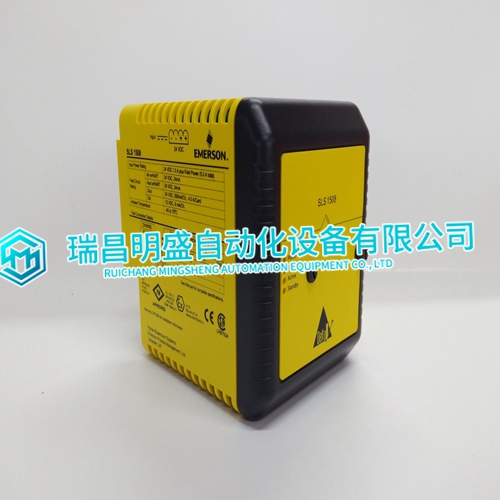
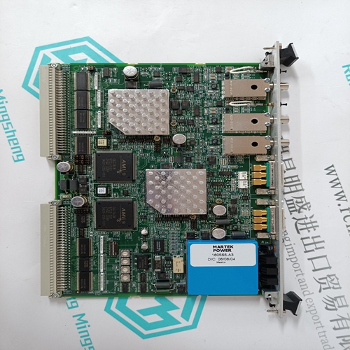
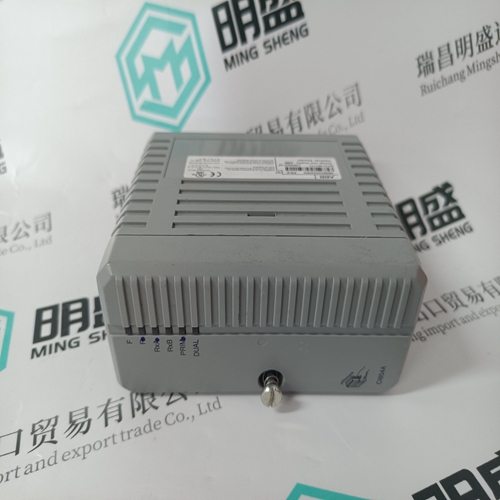
12P3162X162 SLS 1508 Analog input module
- Product ID: 12P3162X162 SLS 1508
- Brand: EMERSON
- Place of origin: The United States
- Goods status: new/used
- Delivery date: stock
- The quality assurance period: 365 days
- Phone/WhatsApp/WeChat:+86 15270269218
- Email:stodcdcs@gmail.com
- Tags:12P3162X162SLS 1508Analog input module
- Get the latest price:Click to consult
12P3162X162 SLS 1508 Analog input module
FCs 215 and 216 in the controller configure the ASI module and identify the active analog inputs. One FC 215 is required for each ASI module. One FC 216 is required for each input channel used on the ASI module. These function codes specify the I/O expander bus address of the ASI module and the channel number on the module connected to a specific analog input signal. The type of the input and the zero and span in engineering units must also be specified to ensure proper scaling and corrections for calibration, cold junction compensation, and nonlinearity correction. Add FC 215 and 216 to the controller to configure the ASI module. Set FC 217 in the controller to calibrate the ASI module or to set the user gain and offset values. Refer to the Function Code Application Manual for more information.
Automatic Adjustments and Corrections
Input processing, calibration, point value calculations, lead wire resistance adjustment, cold junction compensation, gain and offset adjustment, and engineering units conversion are all automatically performed by the ASI module. Input Processing Each A/D converter samples the input signal continuously without need for a start convert command. The A/D output register is updated at a rate determined by the internal filter and can be ready at any time. The ASI module scans all A/D converter output registers at a rate of about 180 milliseconds including calibration and open circuit tests. In addition to the input channels, the built-in cold junction reference is read during normal input scanning
Point Value Calculation
The ASI module maintains a set of adjustment values for each input channel. These values correct for offset and gain errors in the input channel. The raw analog-to-digital converter count value is converted to an actual input signal value using the calibration data. For thermocouple inputs, an adjustment is made for the cold junction temperature of the thermocouple. An additional, user-specified adjustment is then applied, if one has been defined with FC 217. The final corrected input reading is then converted to engineering units using either thermocouple or RTD conversion tables, or the engineering unit zero and span values specified for the input. The following sections describe the various types of input value adjustments.