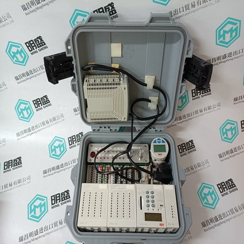
Home > Product > DCS control system > 3BSE018157R1 PM861AK01 Control processor module
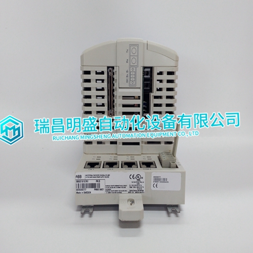
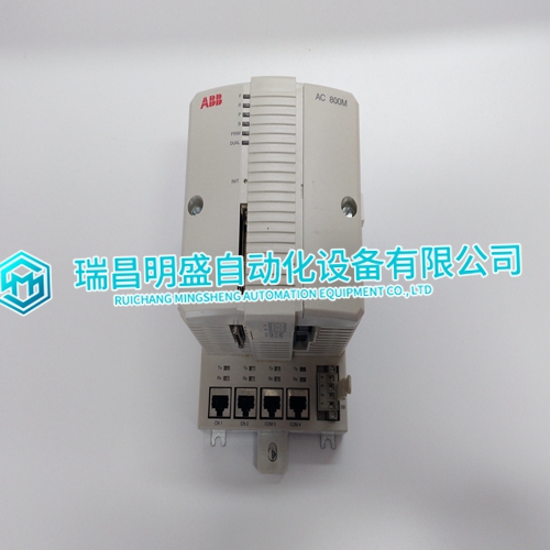
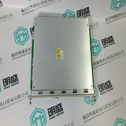
3BSE018157R1 PM861AK01 Control processor module
- Product ID: 3BSE018157R1 PM861AK01
- Brand: ABB
- Place of origin: The Swiss
- Goods status: new/used
- Delivery date: stock
- The quality assurance period: 365 days
- Phone/WhatsApp/WeChat:+86 15270269218
- Email:stodcdcs@gmail.com
- Tags:3BSE018157R1PM861AK01Control processor module
- Get the latest price:Click to consult
3BSE018157R1 PM861AK01 Control processor module
Input Calibration
Each input channel is calibrated at the factory. During the calibration procedure, any offset and gain errors are identified and required correction factors are calculated and stored in the analog input module's nonvolatile memory. These factors are used when the input channel is scanned to correct the reading. A calibration adjustment is applied to active channels and the cold junction reference input.
Cold Junction Compensation
Thermocouple input channels are adjusted for cold junction temperature. The cold junction reference can either be the built-in reference available on the I/O module's termination unit or a value originating from any other function code block output anywhere in the system. The cold junction reference supplied by the controller is assumed to be in degrees C. The ASI module converts this value to millivolts and adds it to the value from the analog-to-digital converter. Thermocouple channels identified to be cold junction reference inputs (FC 216, specification S4) use the built-in cold junction reference on the termination unit for their cold junction compensation.
User Gain and Offset Adjustment
A user-specified linear adjustment can be applied to the input signal before it is converted to engineering units. This gain and offset is applied to the value obtained after all compensation and correction operations are performed. User offset and gain compensates input signals for user corrections. For example, if a 0 to 10 VDC analog input is 0.1 VDC too high, the ASI module can compensate for this offset by adding an offset value of -0.1 for this channel and input type. User gain value is multiplied by volts for high level inputs, by millivolts for low level inputs and thermocouple inputs, and by ohms for RTD inputs. The default user gain is a value of one.

