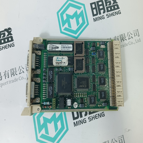
Home > Product > DCS control system > 5SHX2645L0004 3BHB003154R0101 Thyristor module
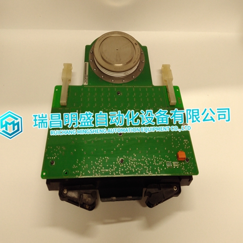
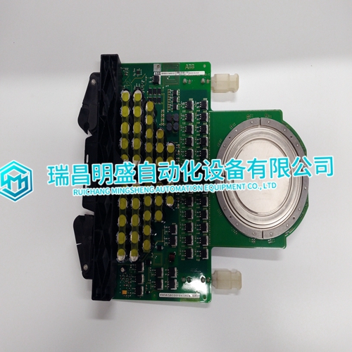
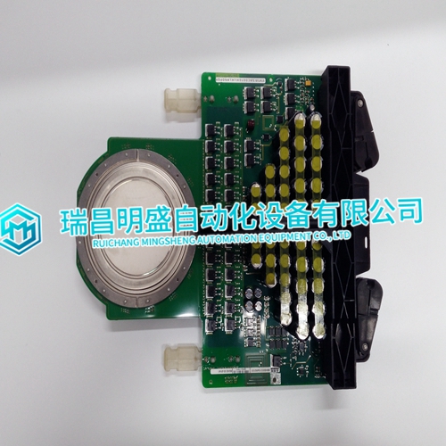
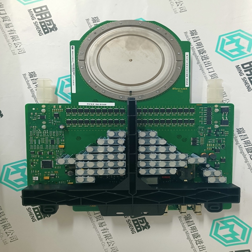
5SHX2645L0004 3BHB003154R0101 Thyristor module
- Product ID: 5SHX2645L0004 3BHB003154R0101
- Brand: ABB
- Place of origin: The Swiss
- Goods status: new/used
- Delivery date: stock
- The quality assurance period: 365 days
- Phone/WhatsApp/WeChat:+86 15270269218
- Email:stodcdcs@gmail.com
- Tags:5SHX2645L00043BHB003154R0101Thyristor module
- Get the latest price:Click to consult
5SHX2645L0004 3BHB003154R0101 Thyristor module
User offset is added to the input signal. Units of offset are specified as volts for high level inputs, millivolts for low level inputs, and ohms for RTD inputs. The default user offset is a value of zero. Separate user gain and offset values can be specified for each input channel and each input type. The user gain and offset values can be set and reset using FC 217. Once defined, user gain and offset values remain in nonvolatile memory and are not lost when module power is interrupted. For more information refer to FC 217 in the Function Code Application Manual.
Engineering Units Conversion
Thermocouple and RTD inputs are converted to the temperature units specified in FC 216, either degrees C or F. Conversion tables representing the voltage (or resistance) to temperature relationship are used for this conversion. The table used in performing the conversion depends upon the input signal type specified. If the input is identified as either millivolt or high level voltage, then the specified engineering unit zero and span values are used to convert the input reading to a scaled engineering unit value. If special calculations need to be performed prior to conversion to engineering units (external to FC 215 and FC 216 blocks), then the zero and span values specified in the function code should be set to represent a standard voltage span for the input. The I/O module FC 216 would then output a corrected voltage input reading which may be processed in the controller through a square root, polynomial, or other function block followed by a scaling function to provide the value in engineering units.
Automatic Calibration
Compensation for drift of input channel circuitry is done by periodic automatic calibration of each A/D converter using an internal precision low-drift reference. This function is transparent to normal input channel processing The IMASI13 module performs built-in tests during power-up and on reset to check the operation and integrity of the module.

