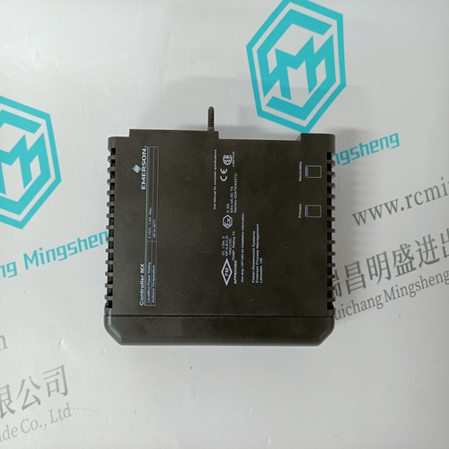
Home > Product > PLC programmable module > ICS TRIPLEX T8311 Interface module
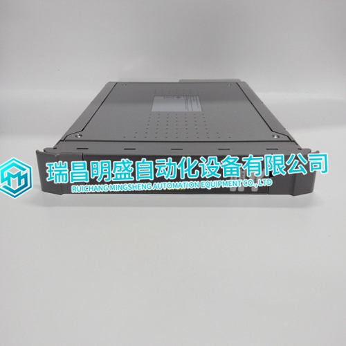
ICS TRIPLEX T8311 Interface module
- Product ID: T8311
- Brand: ICS TRIPLEX
- Place of origin: The United States
- Goods status: new/used
- Delivery date: stock
- The quality assurance period: 365 days
- Phone/WhatsApp/WeChat:+86 15270269218
- Email:stodcdcs@gmail.com
- Tags:ICS TRIPLEXT8311Interface module
- Get the latest price:Click to consult
ICS TRIPLEX T8311 Interface module
Setup and Installation NOTE: Refer to Appendix B for information about replacing an IMASI03 module with an IMASI13 module. Before applying power to the ASI module,
make these checks:
1. Check that the module address is set correctly.
2. Check that the jumpers on the module are set correctly.
3. Be sure the dipshunts in the module mounting unit's I/O expander bus are installed correctly.
4. Check that the jumpers on the termination units are set correctly.
5. Verify I/O cabling connections.
6. Verify there is sufficient logic and field power for the modules in the module mounting unit.
Address Selection Switch (S1)
The ASI module must have an address to communicate with the controller. The ASI module can have any one of 64 addresses (address 0 to 63) on the I/O expander bus. This address identifies the ASI module to the controller and must be the same as the address set in the controller configuration data (FCs 215 and 216, specification S1). Set the address with the eight position address dipswitch S1 (Fig. 3-1). The six right switch positions (three through eight) of S1 set the six-bit address. Positions one and two must remain closed (set to zero) for normal operation The address is set in binary format. Table 3-1 shows some example address settings for switch S1. Refer to Section 6 for the diagnostic settings. Record the I/O expander bus address of the ASI module in the space provided.
Configuring Inputs
Configure the ASI module by setting the specifications in FCs 215 and 216 in the controller and setting the input jumpers on both the ASI module and the termination unit. Refer to Section 4 for more information on configuration and calibration. Each input on the ASI module has a jumper block. The jumper block has different ways it can be configured: millivolt, thermocouple, RTD, voltage and current. Jumper block J1 matches channel one, jumper block J5 matches channel five, jumper block J16 matches channel 16, etc. Each channel can be configured independently. The ASI module can have any number of inputs configured as resistance, low level voltage, or high level voltage.
