Home > Product > DCS control system > GJR5252300R0101 7AC91D Analog module
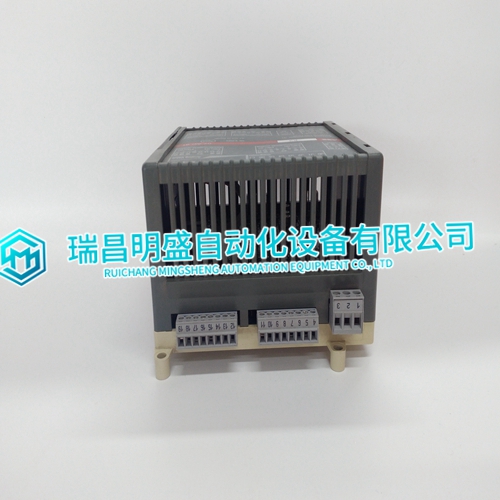
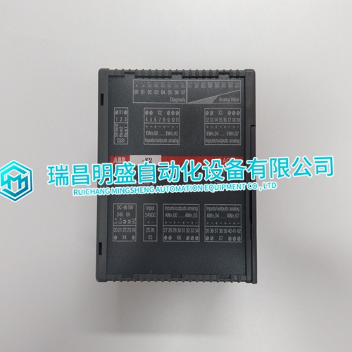
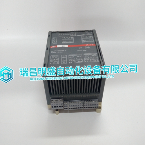
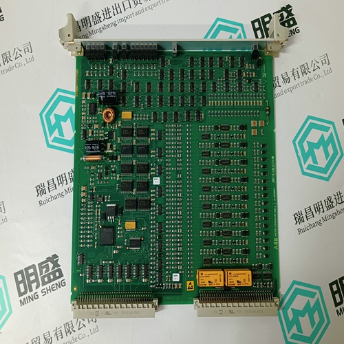
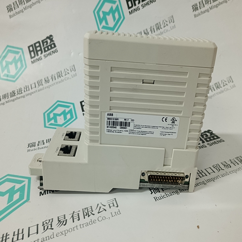
GJR5252300R0101 7AC91D Analog module
- Product ID: GJR5252300R0101 7AC91D
- Brand: ABB
- Place of origin: The Swiss
- Goods status: new/used
- Delivery date: stock
- The quality assurance period: 365 days
- Phone/WhatsApp/WeChat:+86 15270269218
- Email:stodcdcs@gmail.com
- Tags:GJR5252300R01017AC91DAnalog module
- Get the latest price:Click to consult
GJR5252300R0101 7AC91D Analog module
Field Calibration Field calibration is not necessary in normal situations. It is possible to perform calibration procedures in the field if ultra stable, known, precision references are available. Field calibration data is stored in nonvolatile memory. Factory calibration data is stored in a unique nonvolatile memory area. If a field calibration does not provide the desired results, the factory calibration data can be restored. Do this by tuning specification S1 of FC 217 to 11. Signal readings can be compensated by changing the gain or offset of the point signal. In most cases changing these values will take the place of a field calibration. Refer to FC 217, specification S5.
In this example the specifications have these functions:
• S1 selects the field calibration operation (five). The value of five is the set user gain and offset command. • S2 is the block address of the FC 215 which corresponds to the IMASI13 module.
• S3 calls up the channel to be tuned (channel one).
• S4 sets the input type (zero equals millivolt).
• S5 sets the amount of gain. Set S5 to the gain value.
• S6 sets the offset value. Set S6 to the offset value. Check block N+2 or block N+3 to see if the set user gain and offset command is processed correctly, and is incorporated into ASI module input reading of that channel and type. NOTE: Field calibrating all 16 channels for all four input types on an IMASI13 module is a lengthy procedure that may require up to four hours to complete when done properly
A channel can be disabled
and field calibrated separately from the rest of the active channels on the ASI module. Each channel can be calibrated for any of the three input ranges: • Individual channel low level voltage range (-100 to +100 millivolt). • Individual channel high level voltage range (-10 V to +10 V). • Individual channel three-wire resistance range (5 ohms to 500 ohms). To field calibrate each of the four ranges:
1. Configure the point in the system.
2. Disable the point from the system.
3. Calibrate the point with the new value (two calibration points per channel and input type).
4. Enable the point to the system.