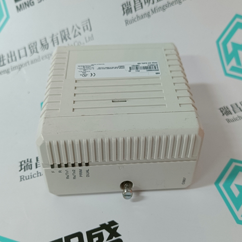
Home > Product > DCS control system > 1X00416H01 WH5-2FF Power supply module
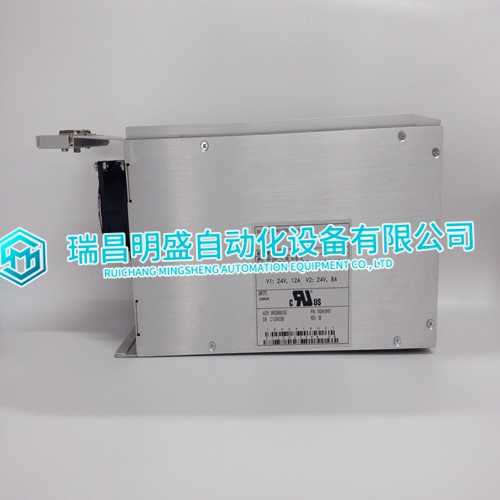
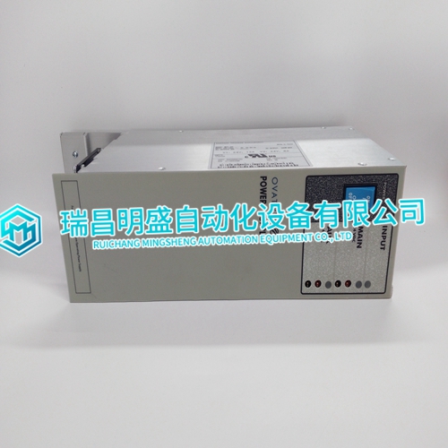
1X00416H01 WH5-2FF Power supply module
- Product ID: 1X00416H01 WH5-2FF
- Brand: EMERSON
- Place of origin: The United States
- Goods status: new/used
- Delivery date: stock
- The quality assurance period: 365 days
- Phone/WhatsApp/WeChat:+86 15270269218
- Email:stodcdcs@gmail.com
- Tags:1X00416H01WH5-2FFPower supply module
- Get the latest price:Click to consult
1X00416H01 WH5-2FF Power supply module
The original ASI module calibration is performed in the factory in a controlled, stable environment. Ambient temperature must remain constant at 25 (±1.0) degrees C. The field calibration location must be free from drafts.After each ASI module is powered-up in its calibration location, allow some warmup time before calibration for the most accurate results. This warmup time should be at least 15 minutes. There are three types of inputs on the ASI module: • Low level voltage range (-100 to +100 millivolt). • High level voltage range (-10 V to +10 V). • Three-wire resistance range (5 ohms to 500 ohms). Each of the 16 inputs can be used as a high level, a low level, or a three-wire RTD input. The high level, low level, and three-wire RTD inputs can be field calibrated with this procedure. ABB Automation recommends checking the accuracy of the channel within each of the specified ranges after calibrating each channel.
Test Equipment Required
The devices required to perform the field calibration are: • One powered module mounting unit slot per ASI module (+5 V with power fail interrupt). • One controller with I/O expander bus dipshunts. • A controller interface device such as a Composer™ or Conductor workstation. • An NKAS01 cable and its termination device (NTAI06). Each input type to be field calibrated requires ultra-stable, known precision sources. Low-Level Voltage Source • -100 to +100 millivolt range with an accuracy of "10 microvolts (or "0.005 percent of this range). • DC output resistance of less than 2.0 ohms.
Individual Channel Calibration
This section provides field calibration procedures for low level, high level, and resistance. To calibrate each channel in the module: 1. Configure the point in the system.
2. Disable the channel.
3. Calibrate the channel with two calibration points.
4. Enable the channel. This example shows the values to tune the FC 217 specifications for a low level voltage range calibration for channel one on the ASI module referenced by the FC 215 at block address 100. S4 of FC 216 must also be set to any of the thermocouple or millivolt types.
