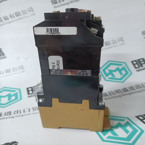
Home > Product > DCS control system > 1C31124G01 Analog input card
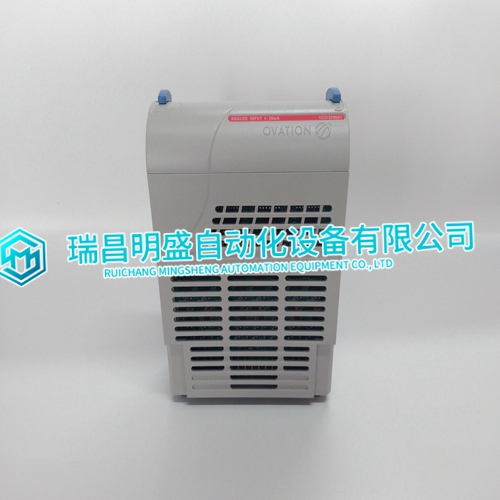
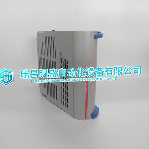
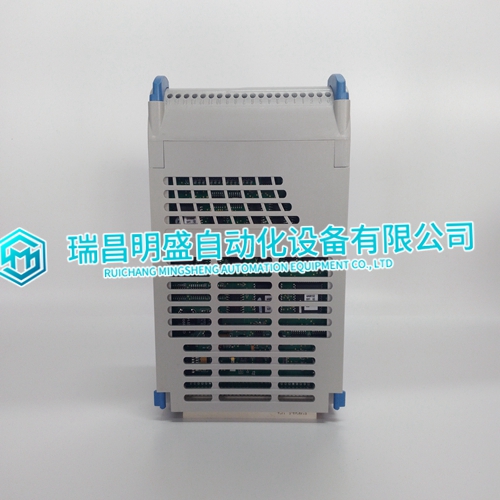
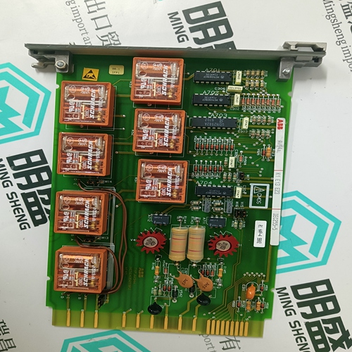
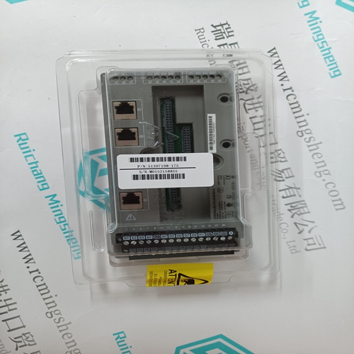
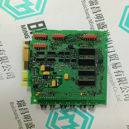
1C31124G01 Analog input card
- Product ID: 1C31124G01
- Brand: EMERSON
- Place of origin: The United States
- Goods status: new/used
- Delivery date: stock
- The quality assurance period: 365 days
- Phone/WhatsApp/WeChat:+86 15270269218
- Email:stodcdcs@gmail.com
- Tags:1C31124G01Analog input card
- Get the latest price:Click to consult
1C31124G01 Analog input card
This example shows the values to tune the specifications to in order to reset the channel field calibration data to the original factory settings for an ASI module at address one. This is needed only if the field calibration is unsuccessful.
The following steps field calibrate channel one for the low-level voltage range of -100 to +100 millivolt. Change specification S4 and use these steps to configure high level, or resistance inputs.
Also S4 of FC 216 must be consistent with the type of calibration being performed.
1. Locate the block address in the controller of FC 217.
2. Verify that the I/O expander bus dipshunts are in place to allow ASI module bus communications.
3. On the ASI module, for each input channel, place the jumpers as shown in Figure 3-3.
4. Set S2 of FC 217 to the block address of the FC 215 which references the ASI module.
5. Insert the ASI module into a powered slot. The green LED will be solid indicating the module is linked to a FC 215 in the configuration.
6. Allow the ASI module to warm up for at least 15 minutes.
7. Put the controller in execute mode.
8. Set FC 217 for the required specifications. After each calibration command is issued by performing a tune operation, monitor the calibration command status to determine if any errors have occurred during the field calibration.
This example calibrates channel one
on the ASI module which is referenced by the FC 215 at block address 100. For low level voltage, disable the desired channel by tuning these values into the specifications. a. Disable point (S1 = 1). b. ASI module referenced by FC 215 at block address 100 (S2 = 100). c. ASI module channel one (S3 = 1). 9. Verify that the low-level voltage source is connected to channel one of the ASI module to be calibrated and the source voltage is set to the full scale value (+100 millivolt). NOTE: Each time the source voltage is changed, at least 15 seconds settling time is required before the point field calibration takes place. If the source itself has a measurable settling time, add this to the 15 second requirement.

