Home > Product > DCS control system > 5X00119G01 Analog input module
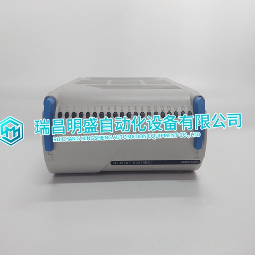
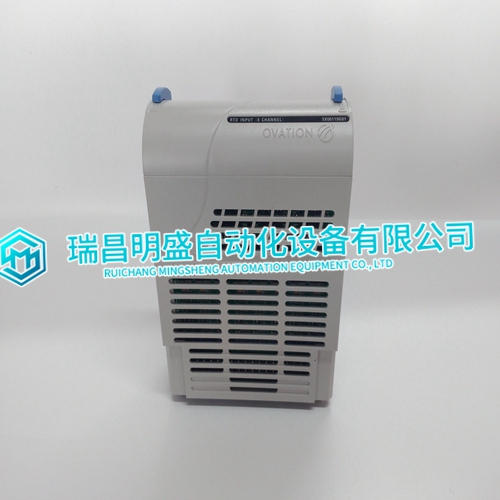
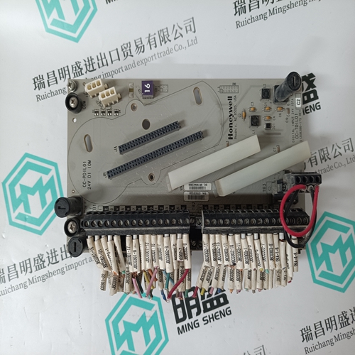
5X00119G01 Analog input module
- Product ID: 5X00119G01
- Brand: EMERSON
- Place of origin: The United States
- Goods status: new/used
- Delivery date: stock
- The quality assurance period: 365 days
- Phone/WhatsApp/WeChat:+86 15270269218
- Email:stodcdcs@gmail.com
- Tags:5X00119G01Analog input module
- Get the latest price:Click to consult
5X00119G01 Analog input module
Successful field calibration operations can be verified by checking for a zero value in FC 217, output N+1 and N+4. If the point calibration was unsuccessful, an error code will appear in the FC 217, outputs N+1 and N+4 which can aid in troubleshooting. 11. Successful field calibration operations can be verified by checking for a zero value in FC 217, outputs N+1 and N+4 for a zero value. If the point calibration was unsuccessful, an error code will appear in the FC 217, outputs N+1 and N+4 which can aid in troubleshooting. At this step, two points have been field calibrated (0 and full scale) and the enable calibration command can be executed. The three input ranges are low level, high level, or RTD. If desired, repeat Steps 7 through 10 for channels 2 through 16 to calibrate all 16 channels on the ASI module.
Startup
Communication between the ASI module and controller starts when the two modules are configured correctly (refer to Section 4). The ASI module address in FCs 215 and 216 must be the same as the address set on the address dipswitch. Upon startup, when power is applied to the ASI module and the controller is put into execute mode, all channels are initially marked bad quality until the controller downloads the configuration data and the ASI module processes a valid input signal
Operation
The controller sends an interrupt command to the ASI module whenever it sends new configuration data. This interrupt causes the ASI module to read the configuration data and initialize its input handling, conversion, and compensation calculations. Once configured by the controller, the ASI module scans its inputs and makes corrected values available to the controller over the I/O expander bus. The controller reads the values from the ASI module during its normal segment cycle operations. Refer to Section 2 for more information about ASI module theory of operation.