Home > Product > Servo control system > WOODWARD 9904-149 Servo control module
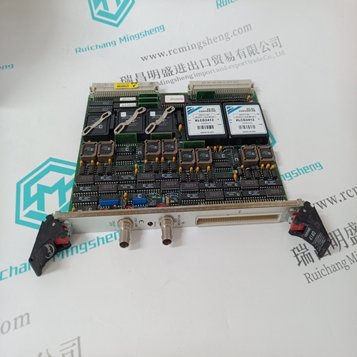
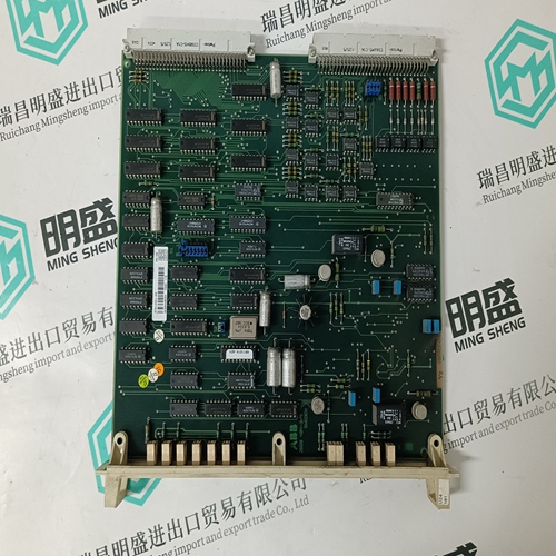
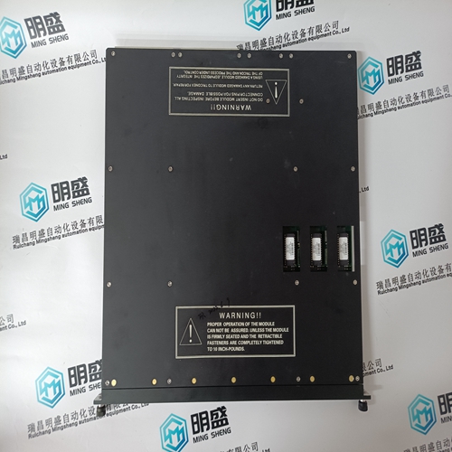
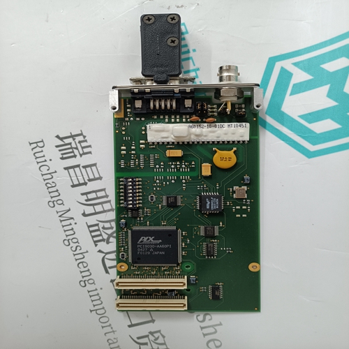
WOODWARD 9904-149 Servo control module
- Product ID: 9904-149
- Brand: WOODWARD
- Place of origin: The United States
- Goods status: new/used
- Delivery date: stock
- The quality assurance period: 365 days
- Phone/WhatsApp/WeChat:+86 15270269218
- Email:stodcdcs@gmail.com
- Tags:WOODWARD9904-149Servo control module
- Get the latest price:Click to consult
WOODWARD 9904-149 Servo control module
When the controller goes from configure mode to execute mode and there is a configuration error, the controller will enter error mode and byte three of the module status will indicate a five for configuration error - undefined input. If the controller goes into error mode, module status byte three may contain a two, three, or five. A two indicates AI reference error, a three indicates Missing I/O, and a five indicates configuration error - undefined input. If the controller goes into error mode and module status byte three contains a two, three, or five, look at module status bytes four and five for the block number of the function code detecting the error. Block four contains the two most significant digits and block five contains the two least significant digits of the error block. For example, if byte four contains a 10 and byte five contains a 42, then block 1042 contains the error. For more information on module status, refer to the appropriate controller instruction.
Error Example
FC 215 for the ASI module and 216 for the active channel need the same address. Check that the address on ASI switch S1; the address in FC 215, specification S1; and FC 216, specification S1 are the same. If the module address in FC 216 is not the same as in FC 215, the controller will enter error mode when attempting to go to execute mode. The error will indicate five, (byte three of module status/error message equal to 05) configuration error - undefined input. Modify the address in FC 215 and the associated FC 216 blocks. The ASI address value set in FC 215, specification S1 and FC 216, specification S1 should match the ASI module address set on S1.
Use a human system
interface to change the configuration data. For procedures on how to change a function code specification, refer to the appropriate instruction for the human system interface being used. The controller generates a local I/O error in the module status if the I/O expander bus is not connected between the ASI module and the controller. Verify that the bus is connected on the MMU backplane. NOTE: Setting FC 215, specification S4 to zero will cause the controller to trip when the IMASI13 module fails. Changing specification S4 to a one causes the controller to continue to operate if the IMASI13 fails or is missing.
