Home > Product > DCS control system > ABB 3BHE024855R0101 UFC921A101 output signal card
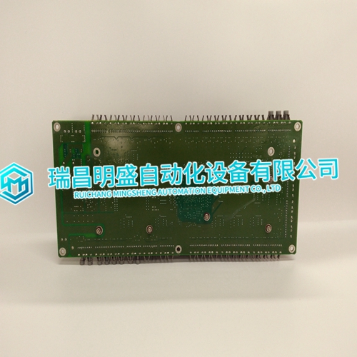
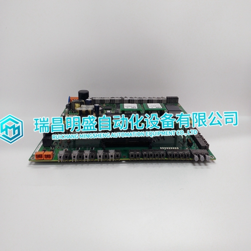
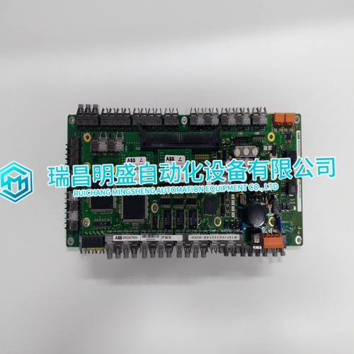
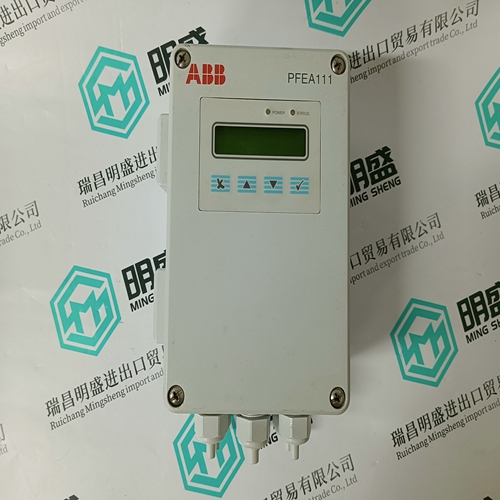
ABB 3BHE024855R0101 UFC921A101 output signal card
- Product ID: 3BHE024855R0101 UFC921A101
- Brand: ABB
- Place of origin: The Swiss
- Goods status: new/used
- Delivery date: stock
- The quality assurance period: 365 days
- Phone/WhatsApp/WeChat:+86 15270269218
- Email:stodcdcs@gmail.com
- Tags:3BHE024855R0101UFC921A101output signal card
- Get the latest price:Click to consult
ABB 3BHE024855R0101 UFC921A101 output signal card
TheABB 3BHE024855R0101 UFC921A101 remote I/O adapter module consists of four major components: diagnostic indicators module switch assemblies field wiring arm Diagnostic indicators are located on the front panel of the adapter module (Figure 1.1). They show both normalABB 3BHE024855R0101 UFC921A101 operation and error conditions in your remote I/O system. The indicators are: • ACTIVE (green) • ADAPTER FAULT (red) • I/O RACK FAULT (red) A complete description of these indicators and how to use them for troubleshooting is explained in chapter 4.
The ABB 3BHE024855R0101 UFC921A101 Assembly is used to select:
• the I/O rack number • the first I/O group number
• I/O scanner communication with or without complementary I/O (for PLC-2 family processors)
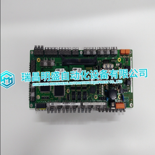
ABB 3BHE024855R0101 UFC921A101 include: • power requirements • module location and keying
• setting configuration plugs
• setting the module switches
• setting the I/O chassis switches (backplane and • setting the I/O chassis power supply configuration plug
• wiring the field wiring arm • installing the terminator resistor
• compatibility of products
• installing the module
Related products:
ABB FDC86-CONT digital controller
ABB DSBC173N 3BNP000468R1 Bus Repeater
ABB DSBB188 3BSE005004R1 Power Bus
