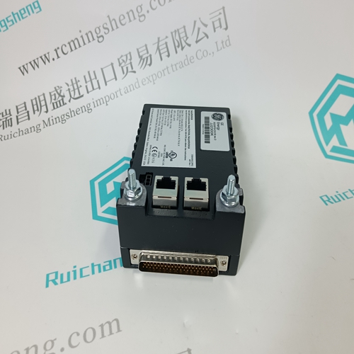
Home > Product > DCS control system > HIEE300936R0001 UFC718AE01 output signal module
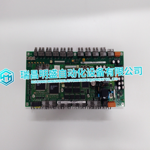
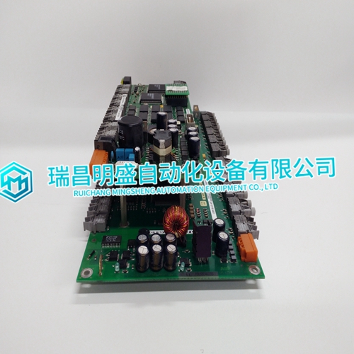
HIEE300936R0001 UFC718AE01 output signal module
- Product ID: HIEE300936R0001 UFC718AE01
- Brand: ABB
- Place of origin: The Swiss
- Goods status: new/used
- Delivery date: stock
- The quality assurance period: 365 days
- Phone/WhatsApp/WeChat:+86 15270269218
- Email:stodcdcs@gmail.com
- Tags:HIEE300936R0001UFC718AE01output signal module
- Get the latest price:Click to consult
HIEE300936R0001 UFC718AE01 output signal module
When you configure your remote I/O system, you must consider: • how to address your I/O • what combination of I/O modules and I/O chassis you can use These topics are discussed in this chapter. Programmable controllers that use the 1771-ASB remote I/O adapter module can address their I/O in 2-slot, 1-slot or 1/2 slot I/O groups. These three addressing methods are referred to as 2-slot addressing, 1-slot addressing and 1/2-slot addressing. You select the addressing method with switch 5 and 6 in the I/O chassis backplane switch assembly. You make this selection for each chassis independently with only one method of addressing for each chassis. I/O groups are made up of I/O terminals (Figure 3.1). An I/O group is an addressing unit that can contain up to 16 input terminals and 16 output terminals. You select an I/O chassis to have either 2-slot, 1-slot or 1/2-slot I/O groups.
Definition
The processor addresses two I/O module slots as one I/O group. Concept: Each physical 2-slot I/O group is represented by a word in the input image table and a word in the output image table. Each input terminal corresponds to a bit in the input image table word and each output terminal corresponds to a bit in the output image table word. The maximum number of bits available for one 2-slot I/O group is 32: 16 bits in the input image table and 16 bits in the output image table. The type of module you install (either 8 or 16-point I/O) determines the number of bits in the words that are used. You select 2-slot addressing by setting switches 5 and 6 of the I/O chassis backplane switch assembly to the OFF position.
I/O MODULE COMBINATIONS
The combination of I/O modules you can use depends on the addressing method and I/O chassis you select. Table 3.A lists acceptable I/O module combinations with 2-slot addressing.
Standard-density I/O modules provide eight input terminals or eight output terminals. Figure 3.3 illustrates the 2-slot I/O group concept with two 8-point input modules. Figure 3.4 shows an 8-point input module and an 8-point output module in a 2-slot I/O group.
16-point I/O modules provide 16 input terminals or 16 output terminals. 16-point I/O modules use a full word in the input or output image table when they are addressed as a 2-slot I/O group (Figure 3.5). Two 16-point modules (one input and one output) can be used in a 2-slot I/O group